Crazy ballon pcb

Retroman839

Senior Member
vacBacker
Feedback
13 (100%)
Credits
8,228CR
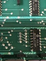
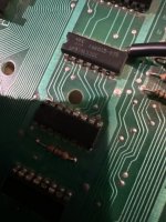
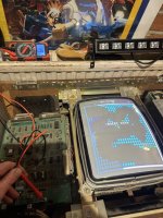
I have this crazy ballon pcb
IMG_1188.jpeg
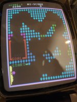
Everything is working except I don’t have the ballon .
At the jamma edge I have 491v

I followed the flow chart
For issues with the ballon IMG_1172.jpeg
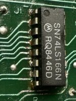
And went straight for this LS166
IMG_1176.jpeg
IMG_1190.jpeg
I want check input and output pins ..
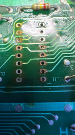
But first .. the corrosion !
toothbrush ? IPA ?
I have a fiber glass pen but feel it’s to abrasive ..
I have removed and reseated the
Double board link harnesses .

That’s it .
Not cleaned the
Pcb apart from rubbing dust off the top of the ls74’s
 
Last edited:

pubjoe

Active member
vacBacker
Feedback
7 (100%)
Credits
866CR
Ah The New Zealand Story prequel!

Was that the Crazy Balloon cocktail on ebay five years ago for a really cheap price? Worthing I think... South anyway. I so nearly talked myself into getting that.

Found some ebay messages with the seller in my email.
IMG_6618.jpeg
 

Macro

Active member
vacBacker
Feedback
4 (100%)
Credits
2,009CR
from my repair log ... so you are looking in the right place!

Only drawing a few pixels of player balloon sprite. Following the schematics, the sprite data from the eprom goes into a 74LS166 shift register at H3, output from this looked suspicious. Replaced this and sprite back to normal.

The biggest pain is the two custom chips, one handles the collision detection and the other does a couple of functions (coin counter, flip screen), but the game will not start without it.

I did write the code for a replacement for the collision detection IC, really ought to program a chip up and see if it works!
 

Retroman839

Senior Member
vacBacker
Feedback
13 (100%)
Credits
8,228CR
from my repair log ... so you are looking in the right place!

Only drawing a few pixels of player balloon sprite. Following the schematics, the sprite data from the eprom goes into a 74LS166 shift register at H3, output from this looked suspicious. Replaced this and sprite back to normal.

The biggest pain is the two custom chips, one handles the collision detection and the other does a couple of functions (coin counter, flip screen), but the game will not start without it.

I did write the code for a replacement for the collision detection IC, really ought to program a chip up and see if it works!
Thanks macro
I’m going to just go clean the 166 up
Look see if I have a replacement
Test activity on the output with logic pen
 

Retroman839

Senior Member
vacBacker
Feedback
13 (100%)
Credits
8,228CR
image.jpg
Will check the 116 output pin asap
.Ordered a new one .

I’m worried about this guy ..
Maybe custom has gone bad .
Does this guy that blows the balloons
Look ok I think he might be behaving incorrectly ? Appearing maybe at incorrect places on screen ?

Is this guy blowing ballon ok ?
 
Last edited:

Retroman839

Senior Member
vacBacker
Feedback
13 (100%)
Credits
8,228CR
Going to try a couple more tests on this 74ls166n shift register .
To start Check clock .. again
Try to determine if I can talk that it is ok

Then Chk

Clock inhibitor see if it’s is held low
Check if clr is held low
See if the Sh/LD has good toggle
Use multi meter on the input pins ..

Maybe after all that I might have an idea of what’s going on with it.
Maybe I won’t have a clue still .

But will be good practice
 

Retroman839

Senior Member
vacBacker
Feedback
13 (100%)
Credits
8,228CR
image.jpgIMG_1375.jpeg
More chip cleaning

166 cane so Piggy backed
Now the guy that blows the ballon’s is behaving himself .image.jpg
Any chip I can get off I will brighten the legs front and back
 
Last edited:

Retroman839

Senior Member
vacBacker
Feedback
13 (100%)
Credits
8,228CR
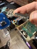
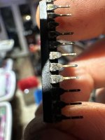
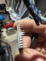
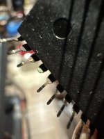
Gotta get that leg out ..🤓
image.jpgimage.jpg
😱 we got long John silver

image.jpg
Cleaned up .. but no leg .

image.jpg

Picked up on underside and goes to a resistor

image.jpg

116 to the right that handles the ballon sprit
image.jpg
Also this ? A random blob of solder under the chip with the bad leg
 
Last edited:

Retroman839

Senior Member
vacBacker
Feedback
13 (100%)
Credits
8,228CR
image.jpgimage.jpg
Revers side looks fresh as the day it was made

On the reverse of the bottom board
IMG_1402.jpeg
That I thought was a ram that had possibly over heated but its jumpers
image.jpg

Traced continuity from the seat pin of broken leg at 3E to a resistor between 4&5 E image.jpg

Under side has continuity
Parts side don’t ..
So good sign 👍
Will solder leg on tomorrow ,

I really don’t think I can retrieve the leg though ..
And I don’t want to remove the seat either 🤔

Start again tommorow when fresh .
 
Last edited:

Retroman839

Senior Member
vacBacker
Feedback
13 (100%)
Credits
8,228CR
Broken leg is only going to the io bus ..
Maybe explains why I could not trigger ram test as I think it goes to the dips .

So I turned my attention back to the main issue.. no ballon .


1793091891716.png
One anoying puddle of solder stuck in a via ..
But so far so good ..
Even though piggy backing did nothing ..

Everything points to the 166 so
It has to swapped for a new one
 
Last edited:

Retroman839

Senior Member
vacBacker
Feedback
13 (100%)
Credits
8,228CR
image.jpgimage.jpgimage.jpg

Pads on underside that are unused couldn’t take the heat and flaked off
Required pads stayed on 😬🫨


Continuity checks out underside
Just need to check top
Poss more solder to top pads.


Forgot to put seat in 🥴 …
Everyday is a school day . Doh!
O well .. I don’t think I will remove it now ,
If it’s good then hopefully this shift register lasts another 45 years.


I have good continuity all over .
Checked & double checked every leg to final location all good ..

Will put stack back together and see what it says
 
Last edited:

Retroman839

Senior Member
vacBacker
Feedback
13 (100%)
Credits
8,228CR
IMG_1429.jpegSame ..
No ballon ..
So that chip was most likely okimage.jpg

Ok so Pin 13 of 166 is stuck low
Corresponding pin
At A1 pin 3 is also stuck low

IMG_1430.jpeg

So I need to go back wards to the inputs on 166 ..


Pin 15 shift load stuck high

Serial input stuck low
Out put. Stuck low ?

So I may have 2 issues then ?

1 for serial input
And another issue for the shift load


Pin 15 of the 116 shift load goes to
Pin 8 at D1 of image.jpg

Does they say 74ls30C ?

Or 74ls306 ?

Ok schematic says IMG_1440.jpeg
pin 8 is the output naturally
 
Last edited:

sukhbir

Active member
Feedback
46 (100%)
Credits
1,699CR
Have you romident the graphics Rom at location 3J?
The data pins should be spitting out data to the 74ls166 input pins if no activity check all address pins on the eprom at 3J.
 
Last edited:
Top