Game: Original Atari Tempest pcb board set.
Purchase Description: N/A. Existing board already in my collection.
Fault: Dead/not running. Player 1 and Player 2 start button LEDs permanently lit, coin meter randomly clicking and game not running.
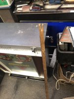
I originally purchased this board set from AndrewB in the US approximately 6 years ago. It has been working fine on the test bench over the last couple of years. I’m currently building a Tempest Cabaret cabinet to house it, that’s when it decides to crap out on me 😢 Not only did the board die, but it has also taken out my defection pcb on the monitor as well
This is the first Tempest board I’ve ever repaired. In situations like this where I am not familiar with a particular pcb, my first port of call is to read as many repairs logs as I can to get a better understanding of what I’m looking at. I came across an old thread on KLOV (thread link here) from a user “mtp66” who had the exact same issue I’m having now. Their problem was a split 39pf mica capacitor at C20.
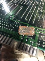
I take a closer look at my board, sure enough the mica capacitor on mine at C20 is also cracked…

There are four 39pf mica caps on the main Tempest board, I check the other 3 and notice the one at C86 in the Analog Vector Generator circuit is also split...

The other two mica capacitors at C92 and C98 look fine.
I order some mica caps and replace the two bad ones. I also have a spare known working WG6100 deflection board, so to save some time (ie., basically ‘cheat’ 🤫) I swop in the good spare deflection pcb and I’ll look at the bad deflection board at a later date (the symptoms are that the spot killer LED stays lit and the screen is dead – my guess it’s a blown transistor in the X/Y circuit or possibly a bad transistor in the spot killer circuit itself – which I’ve had before).
As a side note, when I went to swop in the spare working deflection board, I also tested the monitor frame transistors. One of the power transistors (Q102) was bad but it didn’t blow any fuses. Q102 gets replaced.
With the two new 39pf caps fitted, I power up the Tempest game board but leave the monitor unplugged (deliberately as I want to make sure the game board is good before hooking up the monitor again). The board seems to boot up fine and I play a few games blind to make sure it appears to be playing. I get to game number three and about a minute in there’s a continuous loud sound coming from the speaker – it seems like the game has crashed
I power the game off, then turn it back on. Now the board seems like it is dead again with the occasional random sounds coming from the speaker, and the coin meter randomly clicking over. Back to the repair bench again.
I’m thinking it’s perhaps a socket or CPU issue. My board has had the “Quad” mod done, which is just one EPROM which had 4 game versions. The modification has been done well and the EPROM socket looks clean, so I’d thought I’d take a look at the MPU next.
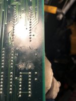
I lift the 6502A chip at C2, and this is what it looked like underneath...

I’m actually quite shocked at the state of the socket. There’s quite a bit of corrosion and it also looks like the remnants of 3 broken legs from a previous old chip that are stuck in pins 21,22 and 24 (circled in red).
The socket has got to go. De-soldering the old socket wasn’t easy, the solder just didn’t want to suck up cleanly. It took me around 2 hours to finally remove the old socket from the board.
With a new 40 pin dual wipe socket fitted, MPU fitted back in, it’s time to power up again (still without the monitor connected).
The game is still not booting/running. All I am getting now is a single click on the coin meter and the P1 and P2 start LED’s constantly lit. It’s consistent every time I power off, then on; just one click on the meter and the two lit LEDs.
Back to the bench, this time with the logic probe in hand. Checking the reset pin 40 on the MPU shows it’s being held high. The clock pin at 37 is mainly high with a faint flash of low on the logic probe. It’s definitely not a clean signal here, so it looks like I’ve got a clock issue. I probe the 193 counter at C4, all the outputs look really weak on the low signals. It’s the same with the hex inverter at A6. There’s not much to the clock circuit so my hunch is that the Q1 (2N3904) transistor is probably the culprit.

With a new 2N3904 fitted, the board seems to power up normally. No clicking on the meter and the player LED’s are off.
I add a credit, the meter correctly clicks once, P1 start LED now flashes and you can play a game. It looks like this game is now fixed
The final thing to do is to check the X-Out and Y-Out voltage readings. I want to make sure they are good before I hook the monitor back up.
In attract mode, I’m getting:-
X-Out (DC): -0.1v to 0.6v
X-Out (AC): - 1.0 to 4.5v
Y-Out (DC): -2.0 to 2.5v
Y-Out (AC): -1.2 to 4.8v
All looks good to me. The brief spikes over 4v only happen for about a second (whilst it is drawing the “Tempest” logo).
Monitor now hooked up and everything confirmed as working again. No errors reported in test mode either
I’m calling this repair done.
Summary
Bad C20 and C86 mica capacitors causing non-booting issue.
Faulty Q1 transistor causing non-booting issue.
Replaced 40 pin MPU socket at C2 due to corrosion and broken legs in socket.
Parts needed for this repair (not including parts required for the WG6100 monitor)
2x 39pf Mica capacitors
1x 2N3904 NPN transistor
1x 40pin DIP socket
Purchase Description: N/A. Existing board already in my collection.
Fault: Dead/not running. Player 1 and Player 2 start button LEDs permanently lit, coin meter randomly clicking and game not running.
I originally purchased this board set from AndrewB in the US approximately 6 years ago. It has been working fine on the test bench over the last couple of years. I’m currently building a Tempest Cabaret cabinet to house it, that’s when it decides to crap out on me 😢 Not only did the board die, but it has also taken out my defection pcb on the monitor as well
This is the first Tempest board I’ve ever repaired. In situations like this where I am not familiar with a particular pcb, my first port of call is to read as many repairs logs as I can to get a better understanding of what I’m looking at. I came across an old thread on KLOV (thread link here) from a user “mtp66” who had the exact same issue I’m having now. Their problem was a split 39pf mica capacitor at C20.
I take a closer look at my board, sure enough the mica capacitor on mine at C20 is also cracked…
There are four 39pf mica caps on the main Tempest board, I check the other 3 and notice the one at C86 in the Analog Vector Generator circuit is also split...
The other two mica capacitors at C92 and C98 look fine.
I order some mica caps and replace the two bad ones. I also have a spare known working WG6100 deflection board, so to save some time (ie., basically ‘cheat’ 🤫) I swop in the good spare deflection pcb and I’ll look at the bad deflection board at a later date (the symptoms are that the spot killer LED stays lit and the screen is dead – my guess it’s a blown transistor in the X/Y circuit or possibly a bad transistor in the spot killer circuit itself – which I’ve had before).
As a side note, when I went to swop in the spare working deflection board, I also tested the monitor frame transistors. One of the power transistors (Q102) was bad but it didn’t blow any fuses. Q102 gets replaced.
With the two new 39pf caps fitted, I power up the Tempest game board but leave the monitor unplugged (deliberately as I want to make sure the game board is good before hooking up the monitor again). The board seems to boot up fine and I play a few games blind to make sure it appears to be playing. I get to game number three and about a minute in there’s a continuous loud sound coming from the speaker – it seems like the game has crashed
I power the game off, then turn it back on. Now the board seems like it is dead again with the occasional random sounds coming from the speaker, and the coin meter randomly clicking over. Back to the repair bench again.
I’m thinking it’s perhaps a socket or CPU issue. My board has had the “Quad” mod done, which is just one EPROM which had 4 game versions. The modification has been done well and the EPROM socket looks clean, so I’d thought I’d take a look at the MPU next.
I lift the 6502A chip at C2, and this is what it looked like underneath...
I’m actually quite shocked at the state of the socket. There’s quite a bit of corrosion and it also looks like the remnants of 3 broken legs from a previous old chip that are stuck in pins 21,22 and 24 (circled in red).
The socket has got to go. De-soldering the old socket wasn’t easy, the solder just didn’t want to suck up cleanly. It took me around 2 hours to finally remove the old socket from the board.
With a new 40 pin dual wipe socket fitted, MPU fitted back in, it’s time to power up again (still without the monitor connected).
The game is still not booting/running. All I am getting now is a single click on the coin meter and the P1 and P2 start LED’s constantly lit. It’s consistent every time I power off, then on; just one click on the meter and the two lit LEDs.
Back to the bench, this time with the logic probe in hand. Checking the reset pin 40 on the MPU shows it’s being held high. The clock pin at 37 is mainly high with a faint flash of low on the logic probe. It’s definitely not a clean signal here, so it looks like I’ve got a clock issue. I probe the 193 counter at C4, all the outputs look really weak on the low signals. It’s the same with the hex inverter at A6. There’s not much to the clock circuit so my hunch is that the Q1 (2N3904) transistor is probably the culprit.
With a new 2N3904 fitted, the board seems to power up normally. No clicking on the meter and the player LED’s are off.
I add a credit, the meter correctly clicks once, P1 start LED now flashes and you can play a game. It looks like this game is now fixed
The final thing to do is to check the X-Out and Y-Out voltage readings. I want to make sure they are good before I hook the monitor back up.
In attract mode, I’m getting:-
X-Out (DC): -0.1v to 0.6v
X-Out (AC): - 1.0 to 4.5v
Y-Out (DC): -2.0 to 2.5v
Y-Out (AC): -1.2 to 4.8v
All looks good to me. The brief spikes over 4v only happen for about a second (whilst it is drawing the “Tempest” logo).
Monitor now hooked up and everything confirmed as working again. No errors reported in test mode either
I’m calling this repair done.
Summary
Bad C20 and C86 mica capacitors causing non-booting issue.
Faulty Q1 transistor causing non-booting issue.
Replaced 40 pin MPU socket at C2 due to corrosion and broken legs in socket.
Parts needed for this repair (not including parts required for the WG6100 monitor)
2x 39pf Mica capacitors
1x 2N3904 NPN transistor
1x 40pin DIP socket