City Connection (Bootleg) info

Jacmar

Active member
vacBacker
Feedback
1 (100%)
Credits
805CR
Just thought worth posting this as it might save someone some time in the future ... and maybe stop them killing their board !!
Had to knock up a jamma adaptor for this bootleg pcb to check how much fixing it needs (it doesn't, it works fine, just needed a clean!) and found it appears to have a unique edge connector for this game (can't find any reference to it anywhere online) .....
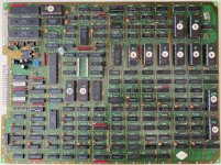
IMG_7864.jpeg

This particular bootleg does NOT use the Jaleco pinout (as you might reasonably assume) , so if you use the Jaleco - Jamma adaptor on this particular bootleg, you will probably fry it ... The correct pinout for this one is as follows:
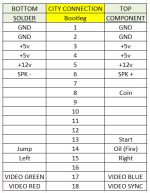
pinout.png

Might help someone out , at some point ... maybe 🤷‍♂️
 

Funhouse71

Active member
vacBacker
Feedback
6 (100%)
Credits
1,021CR
Good info..exactly this reason why I asked the question mating a bootleg Salamander top board to a genuine bottom board in another post on this forum... the bootleggers could have their own pinouts
 

Jacmar

Active member
vacBacker
Feedback
1 (100%)
Credits
805CR
Makes me wonder how this worked back in the day ... did these bootleg boards come with edge connector info for the operator? Or did they just have to work it out for themselves like we do now? Can't imagine they came with any sort of manual like the original boards did ....
 

Gigi502

Newbie
Credits
10CR
Hi Jacmar and thanks for the info.
But, what if i have a bootleg PCB, don't know the name and i have to figure out the pinout from scratch?
I read somewhere to figure out the 5V and ground Lines first, to power the board up and then? How can i search for video outputs, controls input, sound, ecc?
 

Jacmar

Active member
vacBacker
Feedback
1 (100%)
Credits
805CR
Firstly locate and connect up GND and +5v

BOARD UNPOWERED

GROUND - Use your multimeter to trace continuity from edge pins to 74LS TTL ground pins (pin7 if 14 pins, pin8 if 16 pins etc) Usually several edge pads are connected to ground.
+5V - Use your multimeter to trace continuity from edge pins to 74LS TTL +5v pins (pin14 if 14 pins, pin16 if 16 pins etc) Usually at least 2 edge pads are connected to +5v.
+12v - Use your multimeter to trace continuity from the power pin of the audio amplifier (check datasheet).

Once you have ground and +5v connected you can power the board... (you don't need to do 12v yet if you want to leave sound till later)

POWERED

VIDEO SYNC - Use your oscilloscope on edge pads and look for regular digital pulses around 15–16 kHz
RED, GREEN, BLUE - Again scope edge pads. Look for three analogue/video signals, often adjacent (or above/below each other). Exact R/G/B order can be determined by trying them out and if necessary swapping them till correct.

CONTROL INPUTS - Usually sit HIGH (~5 V) and are activated by pulling LOW to GND. Often trace to pull up resistors and/or buffers (eg. LS245) near the edge connector. Once suspected input pins are identified, test them to GND (ideally through a 1KOhm resistor) and note joystick/buttons/coin/start etc.

SPEAKER OUTPUTS - Trace from the audio power amplifier's output. (check datasheet). That will usually lead through a capacitor/filter arrangement towards the connector. You may have: SPK+ / SPK− or audio output / GND depending upon the amplifier arrangement. A scope is also useful here: during attract mode you should see an obvious audio waveform on the speaker output.

This is how I do it anyway
 
Last edited:
Top