You are using an out of date browser. It may not display this or other websites correctly.
You should upgrade or use an alternative browser.
You should upgrade or use an alternative browser.
[SOLVED] Hantarex MTC 9110 - width problems
- Thread starter mawrick
- Start date
yea, I will, was just a quick test (but this is the way it acted before changing the caps as well so I recon this was the main problem (though some of the pots on the remote board where also def bad)nor was i but you need a signal on it really
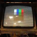
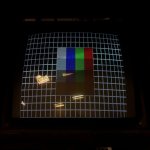
was able to hook up a twin eagle with test screen on, I'v been trying to adjust the different pots, but when it's in sync/hold it's not got the width, I'm kinda able to get it to have somewhat a "scrolling/messy" picture more or less going the full width, but not able to get it to hold, also depending on what is adjusted at the end (seem to vary from settin to setting of the pots) but it will go into protection mode either by the V.freq or the H.freq on the remote board.yea, I will, was just a quick test (but this is the way it acted before changing the caps as well so I recon this was the main problem (though some of the pots on the remote board where also def bad)
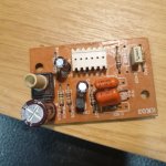
Anyone have any info on what cap size they use on the width cap C37/C38? (as I guess these might vary, at least it seem to have varying information in schematic/part list and that is/was original on it). If I'm doing mod to these I guess I would get a higher value cap to get a wider image?
I can not adjust the width coil as it's stuck (so if I need to do anything with that I'd need to take it out and see if I'm able to loosen it), any idea if it's widest where the core is all the way in or out ?
edit might add the screen is a videocolor 25", and the caps are currently: .33j250 and .033j1000
Attachments
Last edited:
replaced the paralell cap to both being 330nf (as from what I'v read the 25" is supposed to have closer to 0.68uf, after this was the monitor didn't fire up again, and the B+ at the power resistor is aprox 160V (supposed to be 130V), does this mean the TR15 is blown ? (and would such a change of cap cause this?), I'v changed back to the original .033, but still same symptoms so I guess something have fried...was able to hook up a twin eagle with test screen on, I'v been trying to adjust the different pots, but when it's in sync/hold it's not got the width, I'm kinda able to get it to have somewhat a "scrolling/messy" picture more or less going the full width, but not able to get it to hold, also depending on what is adjusted at the end (seem to vary from settin to setting of the pots) but it will go into protection mode either by the V.freq or the H.freq on the remote board.
Anyone have any info on what cap size they use on the width cap C37/C38? (as I guess these might vary, at least it seem to have varying information in schematic/part list and that is/was original on it). If I'm doing mod to these I guess I would get a higher value cap to get a wider image?
I can not adjust the width coil as it's stuck (so if I need to do anything with that I'd need to take it out and see if I'm able to loosen it), any idea if it's widest where the core is all the way in or out ?
edit might add the screen is a videocolor 25", and the caps are currently: .33j250 and .033j1000

(haven't measured any TP as I didn't want to have it running for long) - it did have high voltage on the tube after the initial startup.
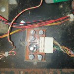
What side of the big resistor is 160V, SP4 (closer to fuses) or SP3 (closer to PTC)? It should be 130V on SP3.
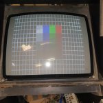
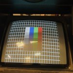
Increasing the capacitance of C37 will make the sides of he picture less compressed with respect to the middle (which is what I see in the grid test screen you posted above). You call it "width cap" but what it does is correct this uneven horizontal linearity (called S-correction).
Increasing the capacitance of C37 will make the sides of he picture less compressed with respect to the middle (which is what I see in the grid test screen you posted above). You call it "width cap" but what it does is correct this uneven horizontal linearity (called S-correction).
What side of the big resistor is 160V, SP4 (closer to fuses) or SP3 (closer to PTC)? It should be 130V on SP3.
Increasing the capacitance of C37 will make the sides of he picture less compressed with respect to the middle (which is what I see in the grid test screen you posted above). You call it "width cap" but what it does is correct this uneven horizontal linearity (called S-correction).
If I measure at the right side of the resistor (if looking from the side directly into it) - on the side that is opposite side where the power connects to, it's been 130V there before I did the change of cap, so suspect I fu** something up ...
Edit: I guess that would be furtherst from the fuses (wasn't in front of it, but dug out a picture)
Took out TR15 and TR20, which seem to check out fine, however would it be normal that both the Base and Emitter pads of T15 goes straight to ground?between 0.5 ohm and 1.5 ohm between base-emiter-ground when tr15 still out of circuit, also D28 seem to check out fine
any tips to further triubleshooting ?
can the transformer be fu*** after that bigger cap ?
any tips to further triubleshooting ?
can the transformer be fu*** after that bigger cap ?
Emitter of T15 does go straight to ground. Base goes to ground through R120 (0.5 ohm, pretty low eh?) and the secondary side of TH1 which is just a wire with very low resistance so yes, that makes you think the base is grounded too. It's regular, move on.
You want to have 130V from the power circuit as all other voltages are produced from that. With yoke connector unplugged the power circuit is separated from the rest of the chassis. Use a light bulb as an alternative load and see what you get from the power regulator circuit.
You want to have 130V from the power circuit as all other voltages are produced from that. With yoke connector unplugged the power circuit is separated from the rest of the chassis. Use a light bulb as an alternative load and see what you get from the power regulator circuit.
Emitter of T15 does go straight to ground. Base goes to ground through R120 (0.5 ohm, pretty low eh?) and the secondary side of TH1 which is just a wire with very low resistance so yes, that makes you think the base is grounded too. It's regular, move on.
You want to have 130V from the power circuit as all other voltages are produced from that. With yoke connector unplugged the power circuit is separated from the rest of the chassis. Use a light bulb as an alternative load and see what you get from the power regulator circuit.
ok, so if I get this correct I can hook up the chasis and do a lightbulb test (and this wont cause any voltage on flyback cap?) and if it's still 160v the fault is most likely on the input side? (voltage reg etc).
Also I guess I only need to hook up the 128V and not the 220V (guess that is only used for degaus?)
haven't gotten around to test it yet, but mine have been powered by a hantarex us250 (135 DC), and I'v also used a 110V AC step down transformer, but read a bit around it should/must have an isolation transformer, is this correct or would it be "safe" to use either the US250 or 110V step down for these tests, and to power it later on ?
Hooked up the light bulb test an it gives me this:
input from hantarex us 250: 134.4V DC
SP4 (Left side of resistor): 104.4
SP3 (Right side of resistor): 133,2
Output of pin 3 (from left side if you look from the resistor side) of the yoke connector: 106,6v
the tr20 have:
1 (b): 108,2v
2 (c): 133,1v
3 (e): 107,7v
I guess these numbers are not good, so any tips on what would cause this behaviour ?
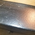
Got it back up and running again, the lightbulb test seem to have "failed" due to to low voltage from the Hantarex us 250 when it gave in 134.4V, hooking up a 110V ac transformer made it come up with somewhat correct voltages, however the main "culprit" was propably a stray soldering "blob" that was sitting underside the boardHooked up the light bulb test an it gives me this:
input from hantarex us 250: 134.4V DC
SP4 (Left side of resistor): 104.4
SP3 (Right side of resistor): 133,2
Output of pin 3 (from left side if you look from the resistor side) of the yoke connector: 106,6v
the tr20 have:
1 (b): 108,2v
2 (c): 133,1v
3 (e): 107,7v
I guess these numbers are not good, so any tips on what would cause this behaviour ?
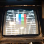
However I'v now added another cap in paralell and have about 0.463mfd on the C37 cap, but still having trouble with my width.
Anyone know if the IC 2 might cause these troubles as well ?., nothing apparent wrong with it, but iirc I'v seen someone had trouble with to much width caused by some errors in this chip (but not 100% positive i remember this correctly).
Attachments
Just thought I'd give a final update on this if anyone else experience this problem in the future.
Finaly was able to sort out the issue and turns out it was due to a short between the legs of C405 on the pincuchon board, still some adjustments to do but seem to be fully working now
Finaly was able to sort out the issue and turns out it was due to a short between the legs of C405 on the pincuchon board, still some adjustments to do but seem to be fully working now