Repoing Universal 4/8 way Joysticks + Buttons

eliotcole

Active member
Feedback
8 (100%)
Credits
1,118CR
Purely asking out of curiousity (maybe interested in buying in the future, if more production is on the table/in consideration) and with zero entitlement or expectation to even being acknowledged, let alone read, or responded to.

I am likely being very dumb ... but ... I don't see the relevance of the bearings in the mechanism ... I am guessing that they anchor the stick to the base bit which hits the switches (or whatever) ... do they simply keep that base level?

Again, purely curious, as I haven't seen bearings in the joysticks I've disassembled and I'd like to know. 🙂


Secondly, I am assuming that this is not even something that I need to ask, as I can see the threads for the ball tops ... but ... I'd assume that shaft covers and 'bat' style tops would also work on these ... should they be something that fits a given cab's style.
 

Phils Arcade

Senior Member
vacBacker
Feedback
10 (100%)
Credits
1,513CR
Purely asking out of curiousity (maybe interested in buying in the future, if more production is on the table/in consideration) and with zero entitlement or expectation to even being acknowledged, let alone read, or responded to.

I am likely being very dumb ... but ... I don't see the relevance of the bearings in the mechanism ... I am guessing that they anchor the stick to the base bit which hits the switches (or whatever) ... do they simply keep that base level?

Again, purely curious, as I haven't seen bearings in the joysticks I've disassembled and I'd like to know. 🙂


Secondly, I am assuming that this is not even something that I need to ask, as I can see the threads for the ball tops ... but ... I'd assume that shaft covers and 'bat' style tops would also work on these ... should they be something that fits a given cab's style.

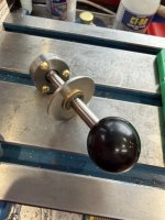
The bearing is the pivot point of the joystick, this is encased in the bearing housing allowing the joystick to move around freely. This fits inside a frame, that has the four leaf switches arranged around the outside. The large silver, washer looking part, halfway up the joystick shaft moves and hits off the tops of the leaf switches, thus pushing the contacts together to give you direction, as you can see from the image below.

img_3281-jpeg.40524


Yeah, the ball top is a standard thread, so you could replace with a bat style top, or shaft covers if you wanted.
 

Phils Arcade

Senior Member
vacBacker
Feedback
10 (100%)
Credits
1,513CR
Well you know the old saying, when the wife's away . . .

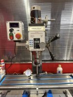
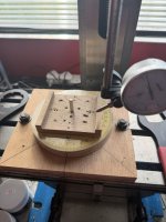
With her indoors gone for the day, it gave me time to get started on the bearing housings. First order of the day was to get the mill trammed back into square. After all the work making the bearing jig and other projects, I needed to ensure the mill head was still true to square to the bed. This involves loosening some nuts and rigging up a dial indicator. You first get the side to side reading done by placing the dial indicator to the left and setting the dial at zero, then swinging round 180° and check if it's still at zero. If not, the divide the difference by 2 and tap on the mill head assembly with a rubber mallet to align. Happy when both read zero. Then onto the front to back. Once all aligned again, time to get started.

IMG_1210 Large.jpeg IMG_1211 Large.jpeg


This will require yet another jig. We need to control the centring of all the drill bits and end mills to do the main bearing holes, especially as these are curved to hold the bearing, but we also need to drill the holes needed for the bolts to pass through. There are three of these set at 120° apart on centre.

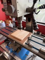
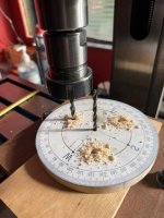
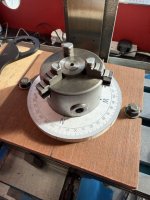
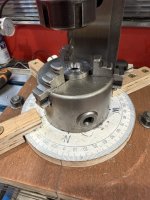
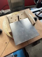
Cut out a piece of 1/2", 18mm, ply to sit across the mill bed, and added two strips that fit into the two outer t-slots. the centre slots were than able to slid along and clamp into the board, you can see this in the third photo below. On top of the base board I added a 1/4", 9mm, board, rounded and with a compass stuck onto it. This was marked out at the required 120°, which aligned with a marking on the bas board. Had to add a couple of hold down clamps to stop it from rotating with the drill bit. A three jaw chuck was then added to that in which to securely hold the bearing housing halves. Everything was aligned centrally and clamped down.

IMG_1213 Large.jpeg IMG_1214 Large.jpeg IMG_1215 Large.jpeg


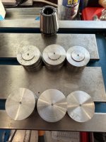
Now onto the parts. We need to mark the centres of both halves to ensure the drill holes are aligned centrally. Drill bits tend to wonder and flex slightly, allowing it to start drilling off centre, which can allow snap your bits, oh err. Once all was marked up, time to start drilling the holes. Start small and move up to till the largest size needed. This reduced any strain on the mill, though does mean a lot of switching bits in and out, and cleaning up after each part is done.

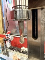
Finally when all the parts are sized out, we move onto the big ballnose bit. This is just slightly larger than the diameter of the bearing, so it can move freely within the bearing housing. The depths were set and off I went. Taking it easy and at low speeds so as not to tax the mill too much. Once each part was done, hovered the metal fragments, turned the part over, and made a slight relief on the opposite side.

IMG_1217 Large.jpeg IMG_1218 Large.jpeg IMG_1219 Large.jpeg


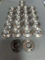
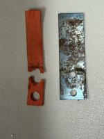
Finally, once finished and after a good clean, it was time to see if the rotation actually worked. Using an original as a guide, I move the mill bed into place, switched out the ballnose bit for a 4mm jobber drill bit, and drilled the first hole. Nice, then the other two, rotating 120° after each. First test fitting, this against an original part. They both matched up brilliantly, so ever onward and upward. You can see the two original halves at the bottom of the last photo.

The first half is now finished, bar some final cleaning and smoothing. I'll get these blackened so to protect them and stop them from rusting. Might be nice to do these in stainless steel as well, though it would mean upgrading the ballnose bit to a carbide version, over $150 a bit, so will see.

Next up will be to drill and tap the other side of the bearing half, and that'll be the joystick and bearing assembly finished.

IMG_1220 Large.jpeg IMG_1222 Large.jpeg


This will now bring me onto the lower part of the joystick frame. The part that the leaf switch attach onto. Need a wee think about this part.
 

Phils Arcade

Senior Member
vacBacker
Feedback
10 (100%)
Credits
1,513CR
As we're heading onto the frame section, a few questions need answering regarding the top section of the frame.

There are quite a few varieties of joystick all based around the same style of shaft and bearing assembly. The lower half of the frame and leaf switches are similar.

The big difference is in the top section and pillars.

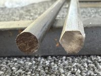
The pillars come in both round bar and hexagonal bar. Some of the frame pillars are welded to the top section, while others are threaded with a nut on the top.

The top section has versions for 4-way, 4-way diagonal, and 8-way. Another has a plastic insert that allows the joystick to support all of the above. Let me know your thoughts on this, as we'll be getting there eventually.

IMG_1225 Large.jpeg IMG_1226 Large.jpeg
 

Phils Arcade

Senior Member
vacBacker
Feedback
10 (100%)
Credits
1,513CR
Okay, I'm just putting this out there.

I've been asked if it's possible to do a "blinged" version of the joystick. The whole thing done in polished brass and stainless steel. Yes I could, but why would you, as it's all hidden inside the cab.

Answer, because I would want one or two.

Obviously this would be a lot more expensive, as the component parts cost a lot more, but they're happy to foot the bill.

Is anyone else interested in this kind of thing? The more the cheaper it would be as buying semi bulk is better. The cost would be just over £180, $200, €200 per joystick, yes you read right, if enough people asked, I could maybe get it to just below that. Then you have shipping costs, and imports tax, if not in the U.K., etc. to think about.

Let me know your thoughts.
 

Phils Arcade

Senior Member
vacBacker
Feedback
10 (100%)
Credits
1,513CR
There's quite a few on the list now, but people always say, add me, or put me down for 4, etc.. but when the time comes, they back out.

I've experienced this too many times. So many people wanted Atari button cones in metal and plastic, I made over a thousand, years ago, and still have hundreds left. Some wanted a batch lot of 50 or more for machines they were fixing up, but then pulled out, so these days I make a small batch, once they go, I'll do another batch, and so on. Usually the second set goes a lot quicker as we've all learned the approach that works, measurements, sourcing materials, jigs, have all been done, so it's basically rinse and repeat.

Think once I get the frame completed, and just the leaf switches to go, I'll start taking orders, and get in contact with those on the list to take, at least a deposit.

Thank you to all who have given their help and support so far.
 

Phils Arcade

Senior Member
vacBacker
Feedback
10 (100%)
Credits
1,513CR
Well the M4 thread tapping bits arrived and this allows me to get the other half of the bearing housing completed. the threes holes drilled, threaded and all holes in the upper and lower halves chamfered. Also made custom length brass screws so they sit just slightly below the surface. They are slightly proud in the photo as the top section of the frame needs to be added.

I've also ordered a pack of circlips to see how they look compared to the e-clips currently holding the actuator assembly in place on the shaft. The circlips are thinner so hopefully look better. Maybe just my OCD.

Photo added of the whole joystick assembly.

IMG_1236 Large.jpeg IMG_1237 Large.jpeg

IMG_1238 Large.jpeg


The bearing housing here is mild steel and is prone to rusting. So need to either heat treat or use a bluing liquid on them to give them some protection.

Next up is the lower frame. Got the 8' x 4' steel sheet, also bought some smaller sheets of stainless steel to try and see what the bling bling version would look like.

Problem is my metal guillotine is hiding behind a load of cabs, in bits, and needs a fair amount of refurbishment. So onto the next side project.

I'll keep you all informed :)

IMG_1232 Large.jpeg IMG_1233 Large.jpeg
 

Phils Arcade

Senior Member
vacBacker
Feedback
10 (100%)
Credits
1,513CR
Wasn't sure if I put this in here or the workshop update thread, but here seems more the right move, as I've already mentioned it above.

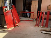
So just before the weekend we had an issue with the metal guillotine being behind a load of machines and more importantly, in bits.

We need this in order to cut the sheet steel down to size. The supplier of the 8' x 4' sheet cut it into quarters, to make it easier to transport, but even that cutting service cost £10, $14. If I wanted them to cut it into the correctly needed size, that's £60, $80. Yes I know it's time taken and wear and tear on equipment, but that seems a little excessive. So pay for the initial cut, and do the rest myself.

First up was getting all those parts out of there. Not an easy task and some of these weigh a fair amount of weight, but for someone who seems to shift cabs around more than they should, all was eventually managed. Next up, finding all the parts. I know there around here somewhere, but where . . .

Guillotine01.jpeg Guillotine02.jpeg Guillotine03.jpeg


All lined up, power hosed and the greasy, oil drenched parts degunked. Everything eventually laid out and working out what goes where.

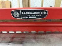
Gave the nameplate a good clean, blacked the background, and polished off the highlights. You can even read the model number now.
and start painting.
Guillotine04.jpeg Guillotine05.jpeg


This is an F.J. Edwards metal treadle guillotine, meaning you use your leg power. Founded in 1916 as the Belgian Specialities Co., the firm formally transitioned into F.J. Edwards Ltd. in 1917. They heavily marketed their sheet metal machinery under the Besco brand name, which this is one of them.

There are two more labels on the side, the makers one and another brass one all covered in paint. Time to see what's hidden beneath.

Guillotine13.png

Guillotine09.jpeg

Hmmm, plant number 58. You can even see the scribe lines to help keep everything aligned. Didn't help much, lol.

Looks like it was originally part of a large manufacturing group, and this was part of plant 58 metalworking shop.

The paint had definitely seen better days. All a range of various colors, chunks taken out, scrapes and a mad amount of rust in some places. This was cleaned down as best as I could, smoothed out the rough spots, and removed the rust. Can't just leave it sitting all multi-colored so let's get mucky

With everything all looking purty, it's time to start assembling. It's all fairly easy to put together, but again, heavy lifting.

Guillotine10.jpeg Guillotine11.jpeg Guillotine12.jpeg


A few test cuts and blade alignment, and she's good to go.

I've a few wee updates I'm looking to do with this. Currently there's no way to ensure your cut is a right angles to the blade, so a nice stop would be good. Also a tape measure so I know how much is at this side of the blade. The cut off part behind the machine, just falls to the floor, so a catch area would be useful, these ol' legs and back aren't what they used to be, lol.

I'll get these added over the next day or two and get cutting. Also have to work out another jig to aligning the holes and cutting the tabs that hold the leaf switches.Maybe this weekend we can start on the lower frame section.
 

Phils Arcade

Senior Member
vacBacker
Feedback
10 (100%)
Credits
1,513CR
Well as another weekend approaches, I had a bit of spare time to try and figure out how to get the bottom of the joystick frame made.

First up was to make a few additions to the metal guillotine from the last update. I added a nice fixed, easy-to-read, 90 degree rule that will make it a lot easier to do quick cuts. Also a moveable long rule that goes right across the bed. This is held in place with two T-nuts and plastic knobs. This makes it a lot easier to make repeated cuts. Measure twice, cut many.

IMG_1283 Large.jpeg


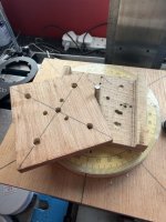
Then onto the parts themselves. I decided to make another rotational jig, similar to the one used for the bearing housing. This has two sets of measurements on it this time, one for the mounting holes for the bearing housing itself, and the others for the frame pillars and leaf switches.

On the rotational jig was added a holder to correctly orientate the piece correctly. First up was to get the measurements right, or as close to it as I could. Cut a number of pieces of wood at the same size, and used those to get a rough pass and do a test fit. After a few tries, it was looking good.

IMG_1293 Large.jpeg IMG_1294 Large.jpeg IMG_1295 Large.jpeg


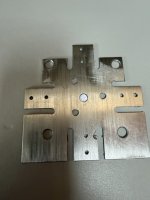
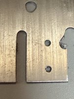
Then onto the actual metal, first attempt shown here. The holes didn't quite align this time, and then you can see the section where the mill cut into the folded wing part. This isn't what you want. I've adjusted the settings slightly again and will have another go over the weekend. Would help a lot if I had a DRO, Digital ReadOut, for the mill. May invest in one as it would make this soooo much easier. Time to check AliExpress, lol.

IMG_1296 Large.jpeg IMG_1297 Large.jpeg IMG_1298 Large.jpeg


I've also ordered the spring steel for the start of the leaf switch assembly and vulcanised insulator paper.
Also, if anyone is interested, I'm currently looking into repoing the SNK multi rotational joystick so keep an eye out for that as well.

IMG_1299 Large.jpeg IMG_1300 Large.jpeg


Once I get the frame, top and bottom, sorted, I'll start taking deposits for anyone looking to order, so start saving those pennies, lol.
 
Last edited:

Phils Arcade

Senior Member
vacBacker
Feedback
10 (100%)
Credits
1,513CR
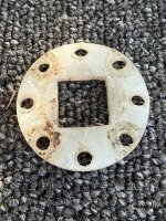
The version I have of the joystick has the ability to select, 4-way normal, 4-way diagonal or 8-way. This is basically achieved via a ring that you rotate and screw into place for 4-way normal/diagonal, or leave off altogether for 8-way. This is the approach I'm going to take for this project, so suits all needs.

The selector is a simply piece of plastic, or nylon, with the square cut out of the centre and a set of eight screw holes around the outer edge which fix to the top of the joystick frame. I ordered a rod of the material to make these, and their minimum order was two of these, so plenty to go around, lol.

Here is the original and the thick rod, oh errr madam.

IMG_1332 Large.jpeg IMG_1333 Large.jpeg


These should be easy enough to make for our needs. I'll probably look at this later today and see what I can come up with.
 

Phils Arcade

Senior Member
vacBacker
Feedback
10 (100%)
Credits
1,513CR
This is totally nuts.

Someone had suggested to use the likes of PCBWay to make the parts, that way I don't have to take time, and energy, source materials, cut and shape, etc... Just buy the parts, put it all together and sell the completed joystick. That sounds like a wonderful idea, after all, they are massive so material and services would be cheap, right!

I decided to add the joystick frame pillars into PCBWay CNC service and put an order for 50 pieces, that's four needed for each joystick. Here is their quote:

1792443518079.png

Works out at nearly $30 per pillar after taxes and we need 4 of them, yup, one for each corner. That's a grand total of $120, just for the pillars.

If I went this route, the joystick would be in the upper 100's of dollars each, so no. I think I'll stick with creating what I can, when I can.
 

Phils Arcade

Senior Member
vacBacker
Feedback
10 (100%)
Credits
1,513CR
Quick wee update.

I've ordered a DRO, to help in making the parts for the mill. Doing the measurements by hand, even with a template, doesn't always come out quite right, or maybe I'm just being fussy.

It's heading this way from China, so will be a few weeks before it gets here, then there's the connecting it up, but should make things so much more accurate, and repeatable.

There's more to do in the meantime and will keep you updated.
 

Phils Arcade

Senior Member
vacBacker
Feedback
10 (100%)
Credits
1,513CR
As we wait for the DRO to arrive, other parts steadily make their way over.

So far the sping steel, electrical paper and leaf switch leaf contact studs are now here, just waiting on the two different leaf metals to arrive and I should be able to start on the leaf switches themselves. Not sure if I should try moulding them like the originals, bit of an experiment that one, or simply create insulators, easier but more tedious, hmmmm.

IMG_1389 Large.jpeg IMG_1390 Large.jpeg
 

Phils Arcade

Senior Member
vacBacker
Feedback
10 (100%)
Credits
1,513CR
A dial micro
Great stuff ..
I just found one of them measuring tools that looks like a stop watch pocket watch .. being a carpenter I didn’t know what it was used for apart from measuring in thousands of an inch etc ..

A dial micrometer, or indicating dial, used to ensure things are concentric when measuring in a lathe, or ensuring a piece is running true to the bed of mill to prevent runout.

This project has shown me how essential these are. For the base frame I roughly honed it in, drilled the holes, then cut out the shape. Only when the shape was cut, you seen that the holes were centred on one part, but off on the opposite side. Looked right before shaping, but only when testing with the micrometer, it was off, just slightly, but enough to make a difference.

So moral of the story is, make sure everything is square before starting. This is where a CNC mill doesn't really care, as it can hone the outside and everything is correctly aligned inside. Really should try and get mine up and running.
 

Phils Arcade

Senior Member
vacBacker
Feedback
10 (100%)
Credits
1,513CR
Makes sence grandads lathe is in the garage .
I wouldn’t know where to start!

Impressive stuff mate keep up the good work cannot wait to see them finished…

Will you do taito spinner next ?🤞😜

Funny enough, the Taito spinner is on my list of things I'd like to do. The large encoding wheel would be a pain in the ass to make, and still on the lookout for an original, unbroken, knob :)
 
Top