SomeGuyIGuess
Newbie
Hi everyone
Here is the fix log for a Sega Rally Model 2A with 3D polygon and texture issues. This is my first adventure in the arcade world, and am happy for any (constructive!) feedback or corrections to the assumptions I've made during troubleshooting.
After picking up a bare cabinet from a member I set about trying to find a game stack to put in it. I found one on eBay complete with the metal shield case, listed as faulty. The issue reported was that it had sync issues, but it had been out of a cabinet for a few years so there were no guarantees on that. I decided to take a chance and hopefully save myself a good amount of money compared to a fully working set of PCBs, and worst case scenario I had the metal shield case I needed and the PCBs could be used for spare parts for another game stack.
It was shipped from the US, and unfortunately the PCB stack had not been screwed in to the metal shield case. With only some scrunched-up newspaper padding it had obviously been rattling around as most of the feet were broken, as was the plastic on one of the connectors to the filter board.
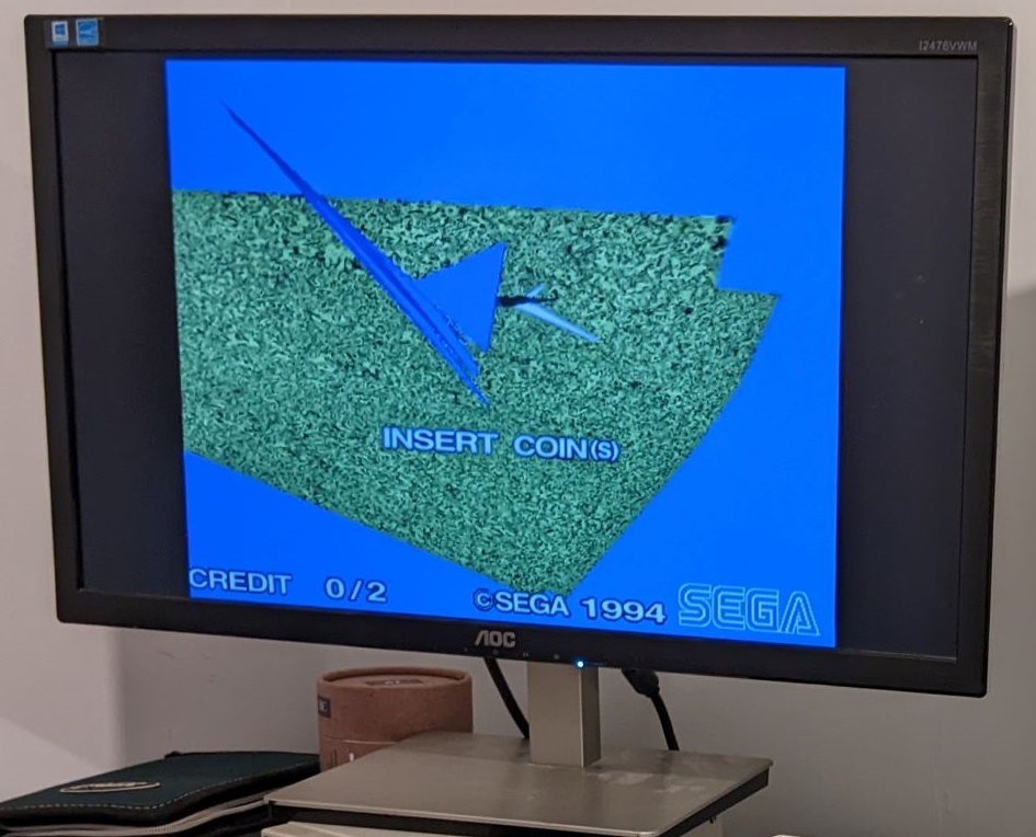
After straightening out a few bent pins on the communications board connector I re-connected the filter board and plugged it in. True to the listing the horizontal and vertical sync were temperamental, but I also found that while the 2D graphics were fine the 3D graphics were not. Instead of the cars and scenery, there were only a few random clusters of polygons, but they seemed fairly stable
Apologies for the lack of good photos/videos, at this point I was too excited to see if this was an easy fix to properly document! I do have this quick video, although after this point the polygon stability settled down. The blue tint to the screen here and in later pictures/videos isn't there to the naked eye and is caused by the warm colour temperature of my room lighting.
First things first I had a quick google and found that the GBS8220 converter I was testing with did not like receiving a 5V sync signal, and while the Red Green and Blue inputs had adjustable trim potentiometers the sync input did not. Adding a 1K resistor in line as suggested largely fixed this, with an adjustment of the clamp settings on the GBS8220 fixing the remaining sync issues. Now we can get a good look at the 3D polygon issue

Checking the ROM board over and comparing to pictures online I found that the TGP 2 ROM (IC17) had been put in backwards!
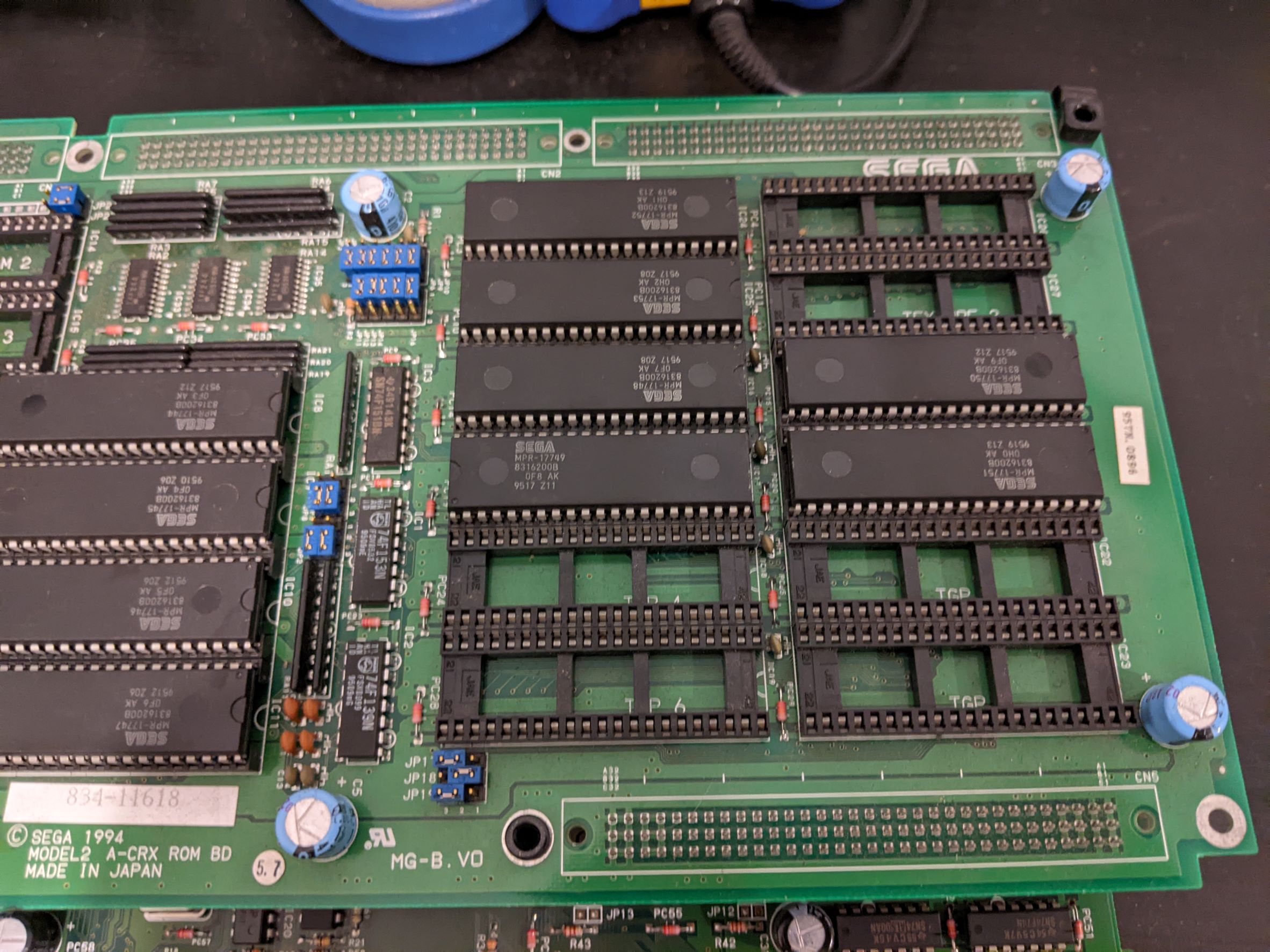
Lesson learned about checking things before plugging them in I also checked the jumpers on the ROM board to find they were all correct. I took the ROM IC out completely initially and found that while some polygons were missing as expected, the polygons that were rendered had corrupted textures but were otherwise correct.

Placing TGP2 back in the right orientation brought the rest of the polygons back, but with the same texture issue. The textures were patterns of mostly random data, but they were being mapped correctly to each polygon meaning the issue was likely with getting the texture data out of the ROM and into the relevant part of the Video Board.
At this point I suspected a bad connection on the ROM board, or a faulty ROM caused by TGP2 being reversed. I removed the Texture and TGP ROMS and did my best to clean the pins, then probed all data and address pins with an oscilloscope to check for signs of life. Each address and data pin showed a clean data signal being received or sent respectively so it didn't look likely to be a damaged ROM.
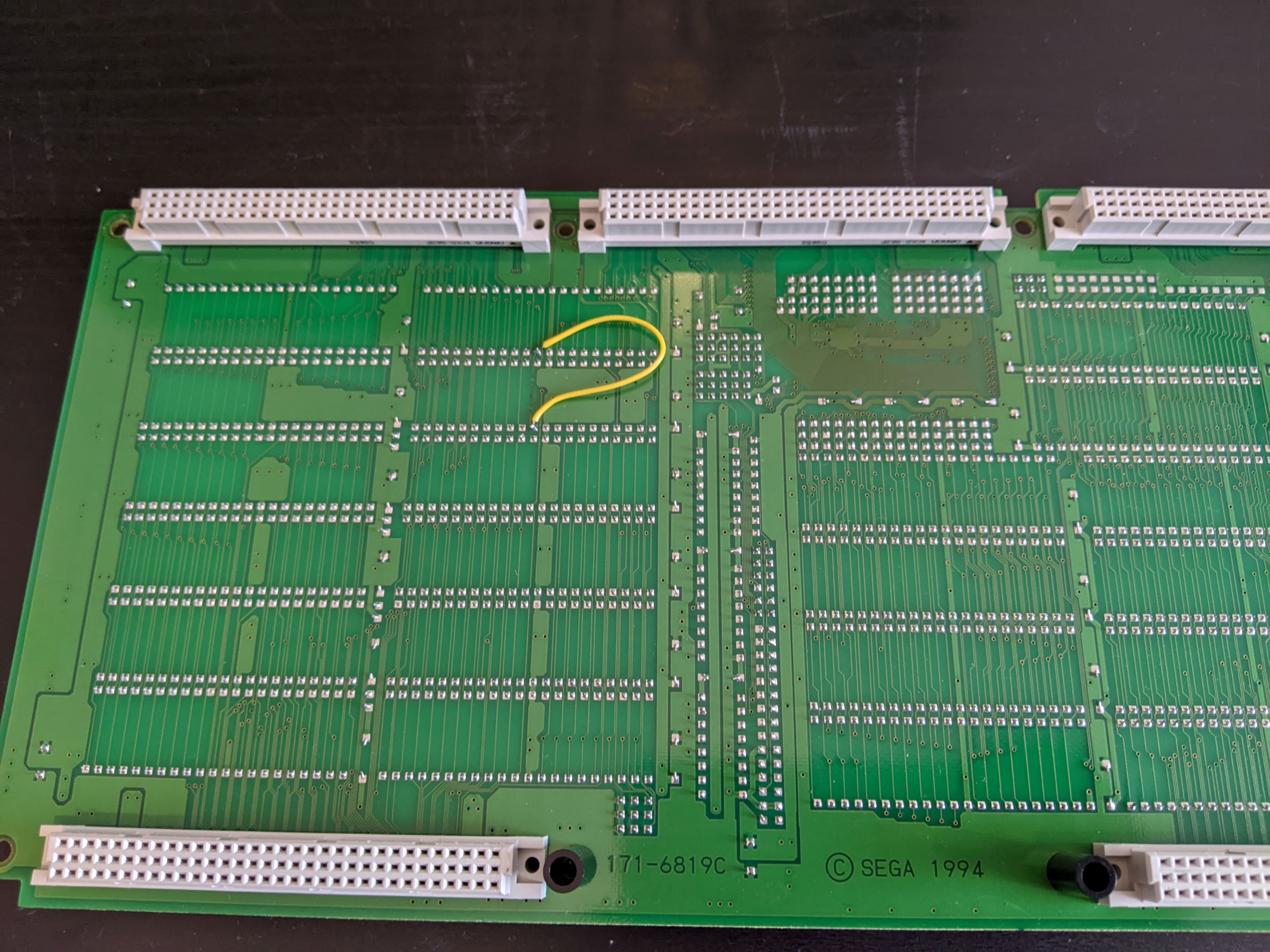
Feeling brave I decided to pull each address and data pin to ground and then 5V one at a time with careful application of a test lead in order to check for differences in the texture patterns that were being mapped to the 3D polygons. Every pin being tied high or low caused a change in the pattern, which indicates that the ROMs were at least mapping each address to a different word of data, and each data bit was being received by the video board. I also reminded myself of the importance of being careful by grounding the BYTE pin which is held high and blowing a trace! Fortunately it was easily repairable and lesson learned...
My attention was now turned towards the video board, and not having access to much information I traced out the address and data lines to find that the TGP ROMS were connected to IC1 (SEGA 315-5644) and the Texture ROMS were connected to IC13 (SEGA 315-5645). After sleeping on it I theorised that IC1 was responsible for getting the polygon data and translating it to it's 3D position, and IC13 was responsible for getting the texture data and correctly mapping it to each translated polygon. I'm still not sure if this is 100% correct but it seems to fit what I've seen.
As the corrupted textures were still being mapped correctly to their respective polygons, it seemed like IC13 was the best place to look next, and I found that lightly tapping the top of the IC or the PCB underneath with the game running caused the texture data to momentarily improve. It seemed that rattling around of the board in the metal shield case during shipping, no doubt coupled with years of running hot, had caused some solder joints to fail.
Now I've done a fair bit of soldering in the past, both through-hole and SMT, but nothing with QFP packages. Reflowing IC13 was a little bit daunting, so given that the RAM chips and IC1 had larger pin pitches and would likely have the same solder failure in future (if not already) I decided to start with the RAM chips and work my way through IC1 to IC13 as practice.
After a lot of reflowing (and fixing some bent pins in IC1 from dragging the iron tip with too heavy hand) I was back in the same place...

Fortunately I did notice that some of the textures were better than before, and this led me to find a pair of shorted pins on IC13 that had been missed in my initial post-repair inspection. Removing this short solved the issue, but only for a short amount of time before it returned.
Returning to the very scientific method of gently tapping the underneath of the video board while watching the output I could see this time the problem was in the area of IC27 (SEGA 315-5646) and IC34 (SEGA 315-5647). After reflowing the pins on these I was greeted with perfect 2D and 3D images! I've let the board run for a number of hours and gently tapped the PCB stack to try and find any other failing connections, and I'm pleased to report that this time the fix seems to be complete!
In time I may reflow the solder on the remaining QFPs on the video and CPU boards as a preventative measure, but for now I decided not to until I've had some more practice.
The only thing I'm a little wary of is that only four of the five green LEDs on the CPU Board light up. I have seen all five light up at a few points during the repair but failed to note this down and now cannot remember at which points I saw this. If anyone can shed any light on what this LEDs indicate I would be very grateful!

Lastly I wanted to thank Lix for his model 2 fix logs, which have been very useful and also provided a great source of encouragement to take this job on!
Here is the fix log for a Sega Rally Model 2A with 3D polygon and texture issues. This is my first adventure in the arcade world, and am happy for any (constructive!) feedback or corrections to the assumptions I've made during troubleshooting.
After picking up a bare cabinet from a member I set about trying to find a game stack to put in it. I found one on eBay complete with the metal shield case, listed as faulty. The issue reported was that it had sync issues, but it had been out of a cabinet for a few years so there were no guarantees on that. I decided to take a chance and hopefully save myself a good amount of money compared to a fully working set of PCBs, and worst case scenario I had the metal shield case I needed and the PCBs could be used for spare parts for another game stack.
It was shipped from the US, and unfortunately the PCB stack had not been screwed in to the metal shield case. With only some scrunched-up newspaper padding it had obviously been rattling around as most of the feet were broken, as was the plastic on one of the connectors to the filter board.
After straightening out a few bent pins on the communications board connector I re-connected the filter board and plugged it in. True to the listing the horizontal and vertical sync were temperamental, but I also found that while the 2D graphics were fine the 3D graphics were not. Instead of the cars and scenery, there were only a few random clusters of polygons, but they seemed fairly stable
Apologies for the lack of good photos/videos, at this point I was too excited to see if this was an easy fix to properly document! I do have this quick video, although after this point the polygon stability settled down. The blue tint to the screen here and in later pictures/videos isn't there to the naked eye and is caused by the warm colour temperature of my room lighting.
First things first I had a quick google and found that the GBS8220 converter I was testing with did not like receiving a 5V sync signal, and while the Red Green and Blue inputs had adjustable trim potentiometers the sync input did not. Adding a 1K resistor in line as suggested largely fixed this, with an adjustment of the clamp settings on the GBS8220 fixing the remaining sync issues. Now we can get a good look at the 3D polygon issue
Checking the ROM board over and comparing to pictures online I found that the TGP 2 ROM (IC17) had been put in backwards!
Lesson learned about checking things before plugging them in I also checked the jumpers on the ROM board to find they were all correct. I took the ROM IC out completely initially and found that while some polygons were missing as expected, the polygons that were rendered had corrupted textures but were otherwise correct.
Placing TGP2 back in the right orientation brought the rest of the polygons back, but with the same texture issue. The textures were patterns of mostly random data, but they were being mapped correctly to each polygon meaning the issue was likely with getting the texture data out of the ROM and into the relevant part of the Video Board.
At this point I suspected a bad connection on the ROM board, or a faulty ROM caused by TGP2 being reversed. I removed the Texture and TGP ROMS and did my best to clean the pins, then probed all data and address pins with an oscilloscope to check for signs of life. Each address and data pin showed a clean data signal being received or sent respectively so it didn't look likely to be a damaged ROM.
Feeling brave I decided to pull each address and data pin to ground and then 5V one at a time with careful application of a test lead in order to check for differences in the texture patterns that were being mapped to the 3D polygons. Every pin being tied high or low caused a change in the pattern, which indicates that the ROMs were at least mapping each address to a different word of data, and each data bit was being received by the video board. I also reminded myself of the importance of being careful by grounding the BYTE pin which is held high and blowing a trace! Fortunately it was easily repairable and lesson learned...
My attention was now turned towards the video board, and not having access to much information I traced out the address and data lines to find that the TGP ROMS were connected to IC1 (SEGA 315-5644) and the Texture ROMS were connected to IC13 (SEGA 315-5645). After sleeping on it I theorised that IC1 was responsible for getting the polygon data and translating it to it's 3D position, and IC13 was responsible for getting the texture data and correctly mapping it to each translated polygon. I'm still not sure if this is 100% correct but it seems to fit what I've seen.
As the corrupted textures were still being mapped correctly to their respective polygons, it seemed like IC13 was the best place to look next, and I found that lightly tapping the top of the IC or the PCB underneath with the game running caused the texture data to momentarily improve. It seemed that rattling around of the board in the metal shield case during shipping, no doubt coupled with years of running hot, had caused some solder joints to fail.
Now I've done a fair bit of soldering in the past, both through-hole and SMT, but nothing with QFP packages. Reflowing IC13 was a little bit daunting, so given that the RAM chips and IC1 had larger pin pitches and would likely have the same solder failure in future (if not already) I decided to start with the RAM chips and work my way through IC1 to IC13 as practice.
After a lot of reflowing (and fixing some bent pins in IC1 from dragging the iron tip with too heavy hand) I was back in the same place...
Fortunately I did notice that some of the textures were better than before, and this led me to find a pair of shorted pins on IC13 that had been missed in my initial post-repair inspection. Removing this short solved the issue, but only for a short amount of time before it returned.
Returning to the very scientific method of gently tapping the underneath of the video board while watching the output I could see this time the problem was in the area of IC27 (SEGA 315-5646) and IC34 (SEGA 315-5647). After reflowing the pins on these I was greeted with perfect 2D and 3D images! I've let the board run for a number of hours and gently tapped the PCB stack to try and find any other failing connections, and I'm pleased to report that this time the fix seems to be complete!
In time I may reflow the solder on the remaining QFPs on the video and CPU boards as a preventative measure, but for now I decided not to until I've had some more practice.
The only thing I'm a little wary of is that only four of the five green LEDs on the CPU Board light up. I have seen all five light up at a few points during the repair but failed to note this down and now cannot remember at which points I saw this. If anyone can shed any light on what this LEDs indicate I would be very grateful!
Lastly I wanted to thank Lix for his model 2 fix logs, which have been very useful and also provided a great source of encouragement to take this job on!

