Hantarex MTC9000 with Orion CRT - Help needed

centrespot

Newbie
Credits
1CR
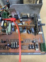
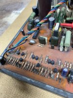
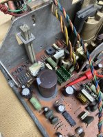
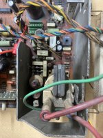
I have a Mercury cabinet with a Hantarex MTC9000 chassis and a Orion 20" CRT, I bought it around 1995 and it worked perfectly, pressure of work made me dry store the cabinet until my retirement. Now when I switch on, the screen is dead and there isn't any static or glow from the CRT.

I am experienced in repairing vintage computers and some of them have CRT's that I have been able to repair but I'm not experienced enough to know all the common terms for the components on a chassis so if you can help me get this all working then please bear this in mind.

I have checked that everything in the cabinet is working by fitting a flat screen monitor and I'm getting 120v supply to the power lead.

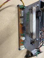
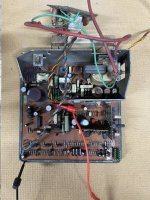
Some of the attached photo's show transistors without their clips, I removed them for some initial tests.

Can someone, with experience in MTC9000 boards, help me get this working ? Please !
 

Attachments

  • IMG_1322.JPG
    IMG_1322.JPG
    155.1 KB · Views: 17
  • IMG_1323.JPG
    IMG_1323.JPG
    128.5 KB · Views: 14
  • IMG_1324.JPG
    IMG_1324.JPG
    112.5 KB · Views: 13
  • IMG_1325.JPG
    IMG_1325.JPG
    131 KB · Views: 14
  • IMG_1326.JPG
    IMG_1326.JPG
    102.3 KB · Views: 14
  • IMG_1327.JPG
    IMG_1327.JPG
    137 KB · Views: 17

tb2000

Active member
Feedback
4 (100%)
Credits
3,306CR
Ok first check that the fuses aren't blown. Only one is for deflection, the other is for the degaussing circuit. Then, with it connected to your crt, get your multimeter and check what the B+ is. Put your red probe in one of the two middle holes on the yoke connector where the black loop of wire is and the negative lead on the chassis frame or heatsink. Turn on the power to the chassis and you should have around 130v. If it's higher than that (in the 160v volt area) you have a horizontal deflection fault. If it's low (below 100v) you have a power supply fault (usually). For the deflection fault i'd check over it for cracks in traces and solder points round the flyback area and HV caps. Check the driver transformer, and the larger power resistors around it. Check the HOT (BU508A), check the HV caps, you might need a new flyback if those are ok. I would imagine you have this problem rather than a power supply fault.
 

centrespot

Newbie
Credits
1CR
Ok first check that the fuses aren't blown. Only one is for deflection, the other is for the degaussing circuit. Then, with it connected to your crt, get your multimeter and check what the B+ is. Put your red probe in one of the two middle holes on the yoke connector where the black loop of wire is and the negative lead on the chassis frame or heatsink. Turn on the power to the chassis and you should have around 130v. If it's higher than that (in the 160v volt area) you have a horizontal deflection fault. If it's low (below 100v) you have a power supply fault (usually). For the deflection fault i'd check over it for cracks in traces and solder points round the flyback area and HV caps. Check the driver transformer, and the larger power resistors around it. Check the HOT (BU508A), check the HV caps, you might need a new flyback if those are ok. I would imagine you have this problem rather than a power supply fault.
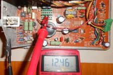
With Black probe on the chassis frame and the red probe on one of the middle wires (black loop) of the green yoke connector plug/socket I get 2.2vdc.
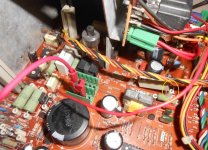
I put the red probe on SP3 and I get 139.8vdc, then SP4 I get 4.4vdc. R105 is warming up and glows red after around 6 seconds.
TR19 Emitter (left pin)= 0.5vdc, Collector (middle pin)= 139vdc Base (Right pin)= 0.3vdc, if I have read the schematic correctly.
 
Last edited:

centrespot

Newbie
Credits
1CR
I've checked a bit deeper, I've lifted legs on resistors and removed transistors to test the components from the power input up to the green yoke connector plug/socket.
All components seem to be good.
I've removed TR15 with the view to doing the bulb load test using a voltage regulator but then decided to de-solder and remove the flyback.
I am now getting 140vdc at the green yoke connector.
 
Last edited:

centrespot

Newbie
Credits
1CR
Have you got the bulb connected to pin 3 where the flyback solders in (what would be pin 3 of the flyback) and ground as a load?
I haven't connected a bulb yet, should I connect it to flyback pin 3 and ground, with the flyback removed.
(I've ordered a new flyback and C36 capacitor 4n7)
I did a bit of continuity testing from pin 3 to SP3, according to the schematic pin 3 goes to R81 but on mine pin 1 goes to R81. I have a very very early chassis and there doesn't seem to be a schematic (on the internet) for it. Some of the component positions differ around the flyback and some parts are just not fitted (D10), C36 is shown as 3n9 but the component fitted is 4n7

(update) Found a different schematic that shows C36 as 4n7 but R81 is still shown as connected to pin 3 of the flyback
 
Last edited:

M K L

Active member
Credits
1,114CR
Measure the resistance of the B+ line to ground. You want to have a high reading here:
DSCN3252.JPG
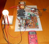
Note that the red croc clip is attached to both pins in the centre so it does the same thing as the jumper wire on the yoke connector. If you have several Kohms here, switch the meter to DC voltage and connect the bulb to the same (or equivalent) points:
DSCN3242.JPG
HOT and flyback are in circuit but are not active because one side of R74 (yellow circle) is lifted from the board:
DSCN3243.JPG
 

centrespot

Newbie
Credits
1CR
Measure the resistance of the B+ line to ground. You want to have a high reading here:
View attachment 62311
Note that the red croc clip is attached to both pins in the centre so it does the same thing as the jumper wire on the yoke connector. If you have several Kohms here, switch the meter to DC voltage and connect the bulb to the same (or equivalent) points:
View attachment 62312
HOT and flyback are in circuit but are not active because one side of R74 (yellow circle) is lifted from the board:
View attachment 62313
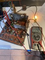
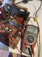
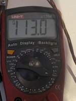
That's virtually the same as my test. I had already removed the flyback and TR15 but still have the CRT connected. My voltage is 114vdc but the resistance is 113ohms
 

Attachments

  • IMG_1337.JPG
    IMG_1337.JPG
    107.8 KB · Views: 8
  • IMG_1338.JPG
    IMG_1338.JPG
    118.9 KB · Views: 8
  • IMG_1339.JPG
    IMG_1339.JPG
    68.6 KB · Views: 7
Last edited:

M K L

Active member
Credits
1,114CR
Repeat the tests with yoke disconnected.

And it's not the same as mine. In your case, with the flyback off circuit, the B+ stops at pin 3 of the flyback. In my case it goes to the HOT collector through the primary winding of the flyback.
 

centrespot

Newbie
Credits
1CR
Repeat the tests with yoke disconnected.

And it's not the same as mine. In your case, with the flyback off circuit, the B+ stops at pin 3 of the flyback. In my case it goes to the HOT collector through the primary winding of the flyback.
I get exactly the same results, 113ohms and 114vdc
For reference, I get 30.6k ohm on pin 3 and 115ohm on pin 4 and 113ohm when connected to both middle pins (3&4) at the green yoke connector
 
Last edited:

M K L

Active member
Credits
1,114CR
https://ibb.co/mCxsGbZ0

Measure resistance of red points (horizontal drive from HOT collector) to ground.
Measure resistance of yellow points (B+ before yoke connector) to ground.
Measure resistance of green points (B+ after yoke connector) to ground.
Measure resistance of pink points (B+ power regulator side = SP4 = emitter of TR20) to ground.
Measure resistance of blue point (SP3 = collector of TR20) to ground.
 
Last edited:

centrespot

Newbie
Credits
1CR
https://ibb.co/mCxsGbZ0

Measure resistance of red points (horizontal drive from HOT collector) to ground.
Measure resistance of yellow points (B+ before yoke connector) to ground.
Measure resistance of green points (B+ after yoke connector) to ground.
Measure resistance of pink points (B+ power regulator side = SP4 = emitter of TR20) to ground.
Measure resistance of blue point (SP3 = collector of TR20) to ground.
Red points are 3.1m and 1.86m
Yellow points are 28.8k and 1.43m (see green point)
Green points (not shown on your photo, unless it is the lower yellow pin 3 on the flyback 1.43m)
Pink points are 28.8k
Blue point is 28.8k

These readings were done with the chassis on the work bench, bulb disconnected, away from the arcade cabinet.
The previous 113ohm readings must have been when the bulb was connected and I'd misunderstood the test.
The reading on the green yoke connector with pins 3 & 4 touching is 28.8k
 
Last edited:
Top