You are using an out of date browser. It may not display this or other websites correctly.
You should upgrade or use an alternative browser.
You should upgrade or use an alternative browser.
Jamma FPGA devkit
- Thread starter lix
- Start date
Fantastic, bet the image displaying was an epic event
nice work

Bytestorm said:WOW this is awesome! I have just been in the same thoughts and installed quartus 18.1 last weekend. Would love one of these units! Really nice that you went with the MAX10. Will you sell these as kits or only preassembled?
I'm not sure just yet about sales, most likely I'll get some quotes for board assembly from various PCB manufacturers first, some in China and couple of local ones here in the UK that I know of. I could sell the bare PCBs though, and just provide a BOM or link to a suppliers shopping trolley so that people can buy their own components to make one. I'll investigate!
Yay! One thing is thinking about a project like this for ages (me), another thing is actually doing it and getting stuff working - good job!
For next rev, I wold consider 4 layer for signal integrity + more decoupling caps for the max10? (not sure what the requirements are, for cyclone 4/10 it's quite a bit).
For next rev, I wold consider 4 layer for signal integrity + more decoupling caps for the max10? (not sure what the requirements are, for cyclone 4/10 it's quite a bit).
kidchameleon
User
Keep up the good work on this
Looks great.
Very envious of:
1. The speed of development (of something that looks fully-formed on arrival)
2. The fact it doesn't catch fire (I'd arse my first proto up).
3. Your SMT oven
I might be in totally the wrong mindset for how this is intended to work, but what's the intention for emulating a game? (say something late 80's, but emulated at a fairly higher level )
1. User uses Quartus to drop in the CPU/Sound cores and do a version of a MAME driver in VHDL/Verilog
2. User drops in your support cores, including generic blitter/tilemap handlers and then maps the graphics to use them (same way MAME works).
3. User drops in an MMC core (I'm guessing they exist - Google says so
 ).
).
4. User programs the FPGA code using a USB blaster.
5. User puts game ROM code onto MMC card.
5. FPGA starts, system copies contents of MMC into RAM and then runs cores.
Aplogies if that misses the obvious - I've never looked at these systems. I do think it's great, even as a blank canvas.?
John Bennett2019-03-27 08:17:54
Very envious of:
1. The speed of development (of something that looks fully-formed on arrival)
2. The fact it doesn't catch fire (I'd arse my first proto up).
3. Your SMT oven
I might be in totally the wrong mindset for how this is intended to work, but what's the intention for emulating a game? (say something late 80's, but emulated at a fairly higher level )
1. User uses Quartus to drop in the CPU/Sound cores and do a version of a MAME driver in VHDL/Verilog
2. User drops in your support cores, including generic blitter/tilemap handlers and then maps the graphics to use them (same way MAME works).
3. User drops in an MMC core (I'm guessing they exist - Google says so
4. User programs the FPGA code using a USB blaster.
5. User puts game ROM code onto MMC card.
5. FPGA starts, system copies contents of MMC into RAM and then runs cores.
Aplogies if that misses the obvious - I've never looked at these systems. I do think it's great, even as a blank canvas.?
John Bennett2019-03-27 08:17:54
I would assume that eventually, if not at the beginning the "developer" user will jump straight to 5, having first downloaded a pre-built core and programmed it to the FPGA (and of course developed some awesome rom code too).
And then I guess there will be "core developer" users that start at item 1 if they don't like the "out of the box" available cores.
That's my assumption (only), and assuming it would be a similar concept to Mist / Mister FPGA
[EDIT] Actually, after typing that out, I just realised that with the available I/O board the Mister can be hooked up to an arcade monitor if you want to and then you can write home-brew for whatever systems have been implemented on there. Which is excellent since the wife has just ordered me one
 It's not great for the rest of the arcade experience though since controls are USB so not as simple as Jamma. OK for dev though.
guddler2019-03-27 14:19:15
And then I guess there will be "core developer" users that start at item 1 if they don't like the "out of the box" available cores.
That's my assumption (only), and assuming it would be a similar concept to Mist / Mister FPGA
[EDIT] Actually, after typing that out, I just realised that with the available I/O board the Mister can be hooked up to an arcade monitor if you want to and then you can write home-brew for whatever systems have been implemented on there. Which is excellent since the wife has just ordered me one
guddler2019-03-27 14:19:15
I've just found this thread today. The board looks great. I'll look forward to following the progress on this.
invzim said:For next rev, I wold consider 4 layer for signal integrity + more decoupling caps for the max10? (not sure what the requirements are, for cyclone 4/10 it's quite a bit).
I did think of adding more decoupling caps, and there are four on the back of the board. Things seem okay at the moment on the power lines, however I'm only using 1300 logic elements at the moment with a 6502 core, video, i2s dac and inputs configured.
Personally I've never done 4 layer board design, I prefer to keep things simple as possible for my homebrew and my commercial circuit design at work. Always 2 layers and all components on one side
I will adventure into multilayer someday!John Bennett said:I might be in totally the wrong mindset for how this is intended to work, but what's the intention for emulating a game? (say something late 80's, but emulated at a fairly higher level )
1. User uses Quartus to drop in the CPU/Sound cores and do a version of a MAME driver in VHDL/Verilog
2. User drops in your support cores, including generic blitter/tilemap handlers and then maps the graphics to use them (same way MAME works).
3. User drops in an MMC core (I'm guessing they exist - Google says so ).
4. User programs the FPGA code using a USB blaster.
5. User puts game ROM code onto MMC card.
5. FPGA starts, system copies contents of MMC into RAM and then runs cores.
All of the above is possible
It's not really set in stone as to how it should operate or be developed for, and I'de hope that people find their own use for it. I initially wanted it as an experimental platform, primarily so I can learn FPGA and get something useful out of learning a new platform.There are indeed plenty of open source FPGA cores for a whole range of peripherals and CPUs, I've had a good explore of opencores to see what is available. It's not plug-n-play mind, there's a lot of connecting logic that has to be written to glue everything together. I did download the Verilog 6502 core and get that running with a rom, some ram and basic IO in a matter of hours though.
As a get-you-started, I'm looking at writing my own logic cores (not a CPU though, that is a little beyond me at this time) that can act just like a basic computer / console / jamma game, and indeed have a bootloader on the MAX10 internal flash that can display a menu and load a program off the SD card. What exact shape that will take I'm not sure just yet, but I'll publish all the info. Any assembled version of the hardware will probably come with this basic system installed.
I find the best way I learn new hardware / software platforms is via tinkering with demos and projects, tweaking things to make them do what I want, then writing from scratch when I'm confident enough.
Back in the late 80's when I still had a ZX Spectrum and everyone around me were all getting Commodore Amigas, I didn't want to be left behind so made my own 256 colour video frame buffer expansion card for my spectrum, which later evolved into a Z80 based SBC which I coded a version of Berzerk for. I still have the source code to a bunch of games I wrote, so I'll look into getting them running and bundling them as examples.
lix2019-03-27 15:17:02
I've been a little quiet on this but still making progress, so just a small update.
I found some issues during testing which I didn't immediately notice, but that is the nature of prototyping! One major problem I discovered was that I'de used some critical configuration pins for the blue colour output DAC, which meant that I couldn't get the FPGA to configure itself on power-up from the internal flash memory. It could only be programmed live via the jtag, and would lose configuration when powered off, kind of negating the point of using the MAX variant.
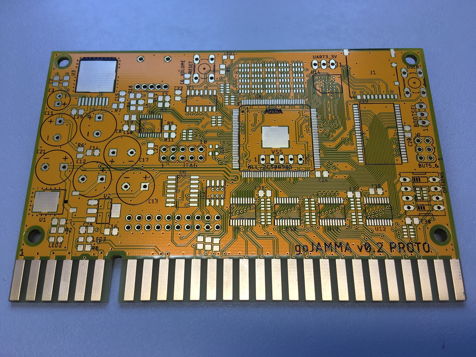
A bit of wire bodging solved the problem, but I thought what with that and a few other issues I had found (like SD card holder being the wrong way round, and the audio amp oversaturating), I thought I may as well jump to version 0.2 and get another batch of PCBs manufactured with the tweaks, so I'll get a few of these populated in the next week and carry on testing.
Otherwise, I did manage to test the various peripherals. The i2S sound DAC works, audio amp works (after adding some attenuation resistors), analog inputs work, 16Mbyte hyperram works, and I've had a 256 colour framebuffer running on the 1Mbyte SRAM.
Also managed to get a 6502 core running and booting a test program from the FPGAs internal flash user memory to write pixels to the framebuffer.
One thing I haven't tested yet is the SD card handling, but I've double checked the wiring, and added a couple of extra IO lines to the card interface so I should be able to bump it up to 4-bit mode. I should be testing that this week, and also hopefully do a bit of work on a blitter.
V0.2:
I found some issues during testing which I didn't immediately notice, but that is the nature of prototyping! One major problem I discovered was that I'de used some critical configuration pins for the blue colour output DAC, which meant that I couldn't get the FPGA to configure itself on power-up from the internal flash memory. It could only be programmed live via the jtag, and would lose configuration when powered off, kind of negating the point of using the MAX variant.
A bit of wire bodging solved the problem, but I thought what with that and a few other issues I had found (like SD card holder being the wrong way round, and the audio amp oversaturating), I thought I may as well jump to version 0.2 and get another batch of PCBs manufactured with the tweaks, so I'll get a few of these populated in the next week and carry on testing.
Otherwise, I did manage to test the various peripherals. The i2S sound DAC works, audio amp works (after adding some attenuation resistors), analog inputs work, 16Mbyte hyperram works, and I've had a 256 colour framebuffer running on the 1Mbyte SRAM.
Also managed to get a 6502 core running and booting a test program from the FPGAs internal flash user memory to write pixels to the framebuffer.
One thing I haven't tested yet is the SD card handling, but I've double checked the wiring, and added a couple of extra IO lines to the card interface so I should be able to bump it up to 4-bit mode. I should be testing that this week, and also hopefully do a bit of work on a blitter.
V0.2:
lix said:I've been a little quiet on this but still making progress, so just a small update.
I found some issues during testing which I didn't immediately notice, but that is the nature of prototyping! One major problem I discovered was that I'de used some critical configuration pins for the blue colour output DAC, which meant that I couldn't get the FPGA to configure itself on power-up from the internal flash memory. It could only be programmed live via the jtag, and would lose configuration when powered off, kind of negating the point of using the MAX variant.
A bit of wire bodging solved the problem, but I thought what with that and a few other issues I had found (like SD card holder being the wrong way round, and the audio amp oversaturating), I thought I may as well jump to version 0.2 and get another batch of PCBs manufactured with the tweaks, so I'll get a few of these populated in the next week and carry on testing.
Otherwise, I did manage to test the various peripherals. The i2S sound DAC works, audio amp works (after adding some attenuation resistors), analog inputs work, 16Mbyte hyperram works, and I've had a 256 colour framebuffer running on the 1Mbyte SRAM.
Also managed to get a 6502 core running and booting a test program from the FPGAs internal flash user memory to write pixels to the framebuffer.
One thing I haven't tested yet is the SD card handling, but I've double checked the wiring, and added a couple of extra IO lines to the card interface so I should be able to bump it up to 4-bit mode. I should be testing that this week, and also hopefully do a bit of work on a blitter.
V0.2:
Great work, keep it up!
Looks interesting.
I'm in the middle of designing something around the MAX10 myself. Great little devices those.
I'll echo the decoupling comment above. Recommendation is 100n close to each supply pin + some larger caps per bank.
Anyway, keep up the good work. Looking forward to seeing the next update.
Dave
I'm in the middle of designing something around the MAX10 myself. Great little devices those.
I'll echo the decoupling comment above. Recommendation is 100n close to each supply pin + some larger caps per bank.
Anyway, keep up the good work. Looking forward to seeing the next update.
Dave
Hi Dave, no, not using the internal oscillator - I did initially specify that as a cost saving measure, ie. avoiding using an external oscillator but after re-reading all the documentation (of which there are a fair amount of gotchas which have caught me out!) I decided to add one externally so I could guarantee accuracy. Started off with a 50mhz osc, but found that some common clock frequencies used in arcade machines couldn't be generated due to certain PLL ratios not being available (another thing only found out during prototyping!), so I changed it to 48mhz, and that seems fine.
I'm keeping a close eye on the decoupling, I've not seen any issues so far but I've not really pushed the logic to the limits yet, so I intend on doing a few more tests.
I've built a few of the most recent yellow 0.2 version prototype, but they all seem to suffer from something going bad in the audio amp circuit. The amp is getting red hot after a few minutes and the +12v line is being pulled down to 6 volts, so either I've got a short somewhere or some bad amp chips (or maybe a dodgy supergun), I'm investigating the issue later. The previous board worked fine sound wise, apart from some clipping due to not matching the output from the stereo DAC to the gain of the amplifier.
Hopefully in the next week I'll publish some tests, maybe have a video of it running some homebrew!
Steve.
Are you driving the negative speaker terminal from one of the amps? The pin could be grounded on the Supergun if it's mimicking a mono Jamma setup.
You'd need a transformer to support both mono and stereo. Edit: scratch that bit. Needs more thought.
DaveSpicer2019-04-26 14:21:11
DaveSpicer2019-04-26 14:21:11
kidchameleon
User
I am watching this with interest!
LewisGamer
Active member
Sign me up for the testing process!
Cheers everyone!
Just a brief update, regarding my last post, I think the sound amp overheating was just an issue with my homemade supergun, took it apart and put it back together and all seemed fine afterwards.
I've been a bit busy with other stuff, Daytona video boards and various other repairs recently, but been putting a bit of time on this again, not as much as I'de like but making some progress. Built up two of the new v0.2 prototype boards and the tweaks definitely fix the last remaining hardware bugs I had.
One of the last parts of the board I needed to test had been the SD card interface, been working on that and implemented a frame buffer with a palette that I can get the 6502 core to write to. Connected an SPI interface up, programmed a small handler to load sectors off the SD card sequentially and write them to the framebuffer and now I can load raw images from the card. Next is to implement Fat32 filehandling and write a small kernel / bootloader so I can get data into the device. Everything else seems to be working well.
Next, I'll be investigating making more of the v0.2 prototype boards and hopefully getting some quotes for PCB assembly. Plus I still want to get more logic written, get some examples up and running, then I'll start putting some hardware / software build files online as open source.
Steve.
Here are the boards I've made so far:

And a frame buffer up and running:

Just a brief update, regarding my last post, I think the sound amp overheating was just an issue with my homemade supergun, took it apart and put it back together and all seemed fine afterwards.
I've been a bit busy with other stuff, Daytona video boards and various other repairs recently, but been putting a bit of time on this again, not as much as I'de like but making some progress. Built up two of the new v0.2 prototype boards and the tweaks definitely fix the last remaining hardware bugs I had.
One of the last parts of the board I needed to test had been the SD card interface, been working on that and implemented a frame buffer with a palette that I can get the 6502 core to write to. Connected an SPI interface up, programmed a small handler to load sectors off the SD card sequentially and write them to the framebuffer and now I can load raw images from the card. Next is to implement Fat32 filehandling and write a small kernel / bootloader so I can get data into the device. Everything else seems to be working well.
Next, I'll be investigating making more of the v0.2 prototype boards and hopefully getting some quotes for PCB assembly. Plus I still want to get more logic written, get some examples up and running, then I'll start putting some hardware / software build files online as open source.
Steve.
Here are the boards I've made so far:
And a frame buffer up and running: