Juno First Boot Leg

NivagSwerdna

Active member
Feedback
1 (100%)
Credits
824CR
Oh dear... I seem to have angered the philmurr gods.... better fix it quick...

2025-03-13_20-41-04.png

2025-03-13_20-43-05.png
Normally I would put some UV cure superglue over the top but it seems reasonably safe. Almost as good as a bought one.

I do have some life from the board...

Screenshot 2025-03-11 21-15-10.png
The image is very intermittent... and obviously not right... but I guess it might not go in the bin just yet.
I recently bought my next board to fix.... so need to get this one done!
 
Last edited:

NivagSwerdna

Active member
Feedback
1 (100%)
Credits
824CR
To stop going around in circles I figured I should properly document some of this...

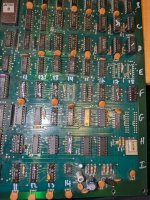
So marking up a grid on the board for reference in removeable white pen....

PXL_20250314_120926479.jpg

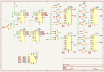
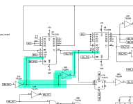
Partial schematic of video section...
JunoFirstBoot_VideoCounters.png
The fact the image above is squeezed in the vertical direction by 4-ish should be a big clue to the problem and normally I would just suspect E18, D18 and D17 since that's where 128V flows... but it seems more subtle than that... Let me re-socket the chips and make sure I haven't broken too many traces and then re-think. All the removed devices test good so they may as well go back.
 

NivagSwerdna

Active member
Feedback
1 (100%)
Credits
824CR
OK... time to give this another go...

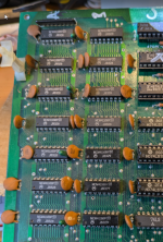
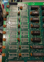
I rather rashly decided to remove and test all the DRAM... (if I had bothered to read the log above I probably would not have done this since quite a lot of the frame buffer obviously works)... anyway I was ****ed off with all the DRAM that made my recent Tutankham repair so annoying so I don't feel too bad...

Before... 16x 4116...

1756496634090.png

Now this is quite fun...
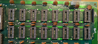
After...

1756496685178.png
The PCB markings are quite interesting.... 8116 not 4116... I've never come across 8116 (and still haven't!)

Seems a 8116 is a single rail 5V version of 4116... (Some 8116 are 5V, some are not... Check the exact model and datasheet!)

There actually seem to be some on EBAY.... "[20pcs] MB8116E 16KBit DRAM DIP16C"

It's almost tempting to get some just for fun.

Anyway...

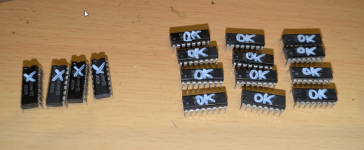
1756496909541.png

So mostly good... 4 duds...

Now do I replace with my static equivalent board... socket and replace the 12 working and use 4 spares... or go rogue and order some 8116s!
 
Last edited:

NivagSwerdna

Active member
Feedback
1 (100%)
Credits
824CR
Well you learn something every day...

Those 8116 chips on EBay are not single rail!
Some 8116 are just 5V but some have the same power requirements as a 4116.
However the 8116 is a drop in replacement for a 4116 and consumes approx 50% of the power.

Not a bad price either... Just ordered 20 off to play with
 

NivagSwerdna

Active member
Feedback
1 (100%)
Credits
824CR
Well there's an afternoon of my life I'll never get back... oh man these things take so much time...

1756571188255.png

1756571222701.png

1756571265387.png

Don't ask me if those are all the original chips... because I might scream and start sobbing. :)
Need to clear some space and then restart the repair... (have to put my original K084 back in another board because I extracted it for comparison recently)...
 

NivagSwerdna

Active member
Feedback
1 (100%)
Credits
824CR
OK... one year later... thought I might try and have another go...

Firstly... I made a change in November 2024-ish...

Was...

1788623929763.png
and I bodged...
1788623969909.png
was I insane? When I compare to the Tutankham Bootleg...
1788624078159.png
Here the two pin 2's are definitely not wired together... there's an inverter between them.. I was obviously barking up the wrong tree.. better put that back before I go again...
... I did plug the board in and I'm getting nothing so back to the drawing board... will fix that first.

(I must have been hallucinating around posts 86 to 88... better undo that and start again!)

Back to square 1...

1788628794227.png
Plug it in and see what is going on...
 
Last edited:

NivagSwerdna

Active member
Feedback
1 (100%)
Credits
824CR
Well if people are interested... a quick diversion into Konami 081 Theory of Operation...

1789113468982.png

Juno First and Tutankham have a 4116 DRAM based Video Frame Buffer and being DRAM it needs refresh and being 4116's it needs row and column addresses each 7 bits wide. On the legit items this co-ordination is provided by a Konami 081 custom but on the bootlegs it is done in 74 series logic. Interesting the implementations do seem to differ between the bootlegs... but more of that later.
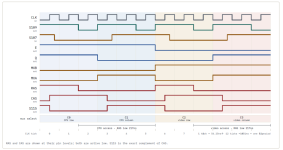
The Konami 081 (or equivalent) basically divides time into 4 sections repeatedly. The first is CPU access... here MXB is low allowing the CPU to drive the address bus. MXA is flipped half way through to split the 14 bits into two pairs of 7 bits and these are loaded on the falling edges of RAS and CAS. During the second half the Video counters drive the address bus and the same effect is achieved. So the video reads and the CPU read/writes are interleaved. The whole video read cycle goes around fast enough that the DRAM stays refreshed (all it needs is a read).
The timing of the edges of MXA, MXB, RAS and CAS relative to each other are critical and that's what I am working on currently...
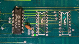
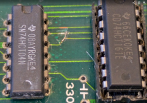
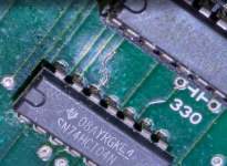
What is interesting is that if this were pure logic in the implementation then the edges would not line up correctly and this is what I am investigating currently... I think this is the purpose of the 300pF capacitor and I suspect my problem is the specific 74LS161 I have swapped... the 300pF acts as an edge delay but is dependent on the input impedance of the counter (to form an RC circuit)... but I am reverse engineering as I go so it's a slow process.
And I have to find the 300pF I removed a year ago... must have put it somewhere!
 

Retroman839

Senior Member
vacBacker
Feedback
13 (100%)
Credits
7,954CR
74ls fires faster than Konami’s 081 custom and the caps slow it down ..
10-15ns

Is this the

small capacitor tacked directly onto Pin 7 of a 74LS161 counter to ground, which manually drags down the duty cycle of the pixel clock to stabilize the core loop.?
 

NivagSwerdna

Active member
Feedback
1 (100%)
Credits
824CR
I think one of my problems is voltage droop... I can get 5.6V at the ribbon cable but this is dropping to 3.9V at the far bottom right hand corner... my 4116s are running VERY hot but I know they do...

Could this be power supply? Presumably it is not since I can get 5.6V to the board.

Maybe the 4116s (and the CPU) which are running very hot are stealing my volts?

I'm tempted to replace the 4116 with something less power hungry but that is quite extreme
 

Retroman839

Senior Member
vacBacker
Feedback
13 (100%)
Credits
7,954CR
When a bootleg is new ..
The voltage may have flowed better all over the board .

Total resistance may have increased as electrolytics dry

Some of your 74ls logic may require
4.7v to 5.1v
 

Georgian2

Active member
Feedback
12 (100%)
Credits
1,868CR
I think one of my problems is voltage droop... I can get 5.6V at the ribbon cable but this is dropping to 3.9V at the far bottom right hand corner... my 4116s are running VERY hot but I know they do...

Could this be power supply? Presumably it is not since I can get 5.6V to the board.

Maybe the 4116s (and the CPU) which are running very hot are stealing my volts?

I'm tempted to replace the 4116 with something less power hungry but that is quite extreme
Most likely one or more are shorted and draw a lot of power. If they are not socketed, you may snip the vcc pin starting with the most hot one and see when the vcc is rising up... Quick but not so nice.
 

NivagSwerdna

Active member
Feedback
1 (100%)
Credits
824CR
I'm still figuring out how to do this... I measured the rail resistance and get max 0.2 ohms across the board. Across the rails is around 270 ohms all around the board.
I have removed all the DRAM and the CPU, the PALs run quite hot but measure OK out of circuit.
Tempted to buy a thermal camera but chatgpt tells me I need to be more persistent.
There are no obvious candidates that I can see
 

Georgian2

Active member
Feedback
12 (100%)
Credits
1,868CR
Could be an shorted capacitor too. Such faults are hard to find. Thermal camera helps too but is expensive.
i usualy set an powersupply to a low voltage like 2-3V and maximum amperage and see what is getting warm or hot.
 

NivagSwerdna

Active member
Feedback
1 (100%)
Credits
824CR
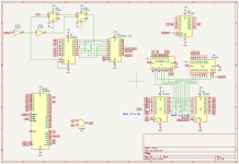
I am awaiting for some electrolytics since as suggested these might be a problem and I may as well swap them out... they are pretty crusty... I thought I would spend some time revisiting the section of the board that emulates a Konami-1 using a 6809E... I know this stuff is pretty well known but the implementation here is quite interesting...
1790445264255.png
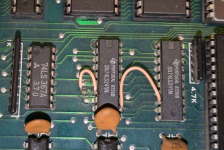
I actually found some problems along the way... looks like I failed to fix a break I spotted earlier and found another one... will have to really delve deep there...
There was a bodge wire I removed but I thought I had repaired the trace... and another one!
Anyway...
It's quite interesting and I don't think I have seen this before...
The PAL at F6 munges the D1,D3,D5,D7 bits of an opcode with A1,A3 when an opcode is detected; matches the logic in MAME. F8 passes the other bits through unchanged.
The most interesting bit is 9F which is a latch that captures an opcode. This is then fed into the PAL F10 that does the opcode detection. The fun part here is that it handles 0x10 and 0x11 prefixes... the 6809 instruction set expanded from a single byte for opcode to have an additional page 2 and page3, so a 0x10 op and 0x11 op are two byte op-codes. To detect 0x10 and 0x11 you don't need D0 so that is not routed to the PAL and only the other 7 bits are decoded. On seeing the prefix byte the opcode munging extends to the second byte. Very clever. G9A and H13A provide the LIC delay.
The PAL equations earlier in the thread appear correct.
So I will repair the breaks and wait for my electrolytics to arrive.
I did buy this board to understand how the bootleggers had replaced the customs rather than to necessarily fix it... looks like I am getting my money's worth!

PS
1790446018844.png
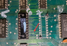
These were the bodges I removed... looks like my repair didn't work... will look harder! (They correspond exactly to the breaks on the schematic).
 

Attachments

  • JunoFirstBootlegK1Section.pdf
    184.1 KB · Views: 2

NivagSwerdna

Active member
Feedback
1 (100%)
Credits
824CR
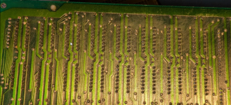
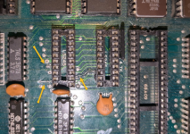
Near F6 there is a cut track. This seems to be a factory modification to fix a PCB error... this cuts the connection from the net of pin 8 of F6 (PAL), pin 8 of D8 and pin 12 of D7 to CPU_D1...

1790452647074.png

and a bodge wire on the bottom from pin 12 of F6 carries the real munged CPU_D1.


1790452706722.png
So that just shows it was confusing enough that the original designers got that one wrong! The cut track and the bodge wire remain!
 

NivagSwerdna

Active member
Feedback
1 (100%)
Credits
824CR
1790503531834.png
Breaks repaired and no need for the flying wires on the top anymore... I guess they were factory too. In particular the trace between pin 12 and across to pin 8 barely exists on the original PCB... maybe a manufacturing glitch. Anyway buzzes out OK now... back to the voltage drop...
 
Top