I want to share a recent project that I’ve wanted to do for a while now to create a simple replacement solution to the generally unreliable official Midway AUX pcb board to upgrade a Pac Man game to MS Pac Man.
Pictured below is the official upgrade AUX pcb board that is needed to upgrade an original pcb to MS Pac Man. It’s a simple conversion that involves removing the Z80 from the Pac Man board, plug in the 40 pin cable going to the AUX pcb into the original Z80 socket at 6B, re-fit the removed Z80 processor onto the AUX board and replace the 2 Pac Man graphic roms at 5E and 5F on the original Pac Man pcb with MS Pac Man eproms.

The problem here is usually the 40 pin cable connecting between the Pac Man board and the AUX pcb. The cable is prone to failure, usually breaking at some point especially near the connector pins. Other issues are sometimes the sockets on the AUX pcb, they are the typical sockets Midway used and connection isn’t always great. There’s the further issue that because the AUX is an add on pcb connected via a cable, it needs to be secured somewhere to stop it from dangling loose. An original metal bracket was made for these to be mounted inside the wall of a cabinet but they are often missing nowadays.
Now I know you can modify an original Pac Man pcb to do away with the AUX board. However, this involves soldering in extra sockets, adding wires and cutting tracks etc., plus the replacement MS Pac Man roms required to make it work are actually bootleg roms. I like to keep everything original if I can so I wanted to create a simple plug-in solution that involves no soldering or hacking on the original Pac Man board.
Here’s what I’ve come up with…

My own reproduction pcb is a combined Sync Buss controller and AUX pcb in one. It plugs into both the Sync Buss socket at 6D and the Z80 socket at 6B. It’s basically the two separate schematics of the Sync Buss and AUX board re-arranged onto one pcb. Since it has been created using the original schematics, it needs the original 4x CG820/CG821/CG822/CG823 MS Pac Man custom chips and the normal MS Pac game roms for it to work. The entire footprint of the repro pcb is actually smaller than an original AUX pcb. The two small holes on the repro board line up nicely with the original holes at 6D if you want to add a cable/zip tie for added stability.
You can even use it as just a standalone Sync Buss controller (to play just Pac Man) by either not soldering any of the MS Pac Man sockets nor the Z80 socket (and just solder the pins for the 28 pin socket at 6D)…
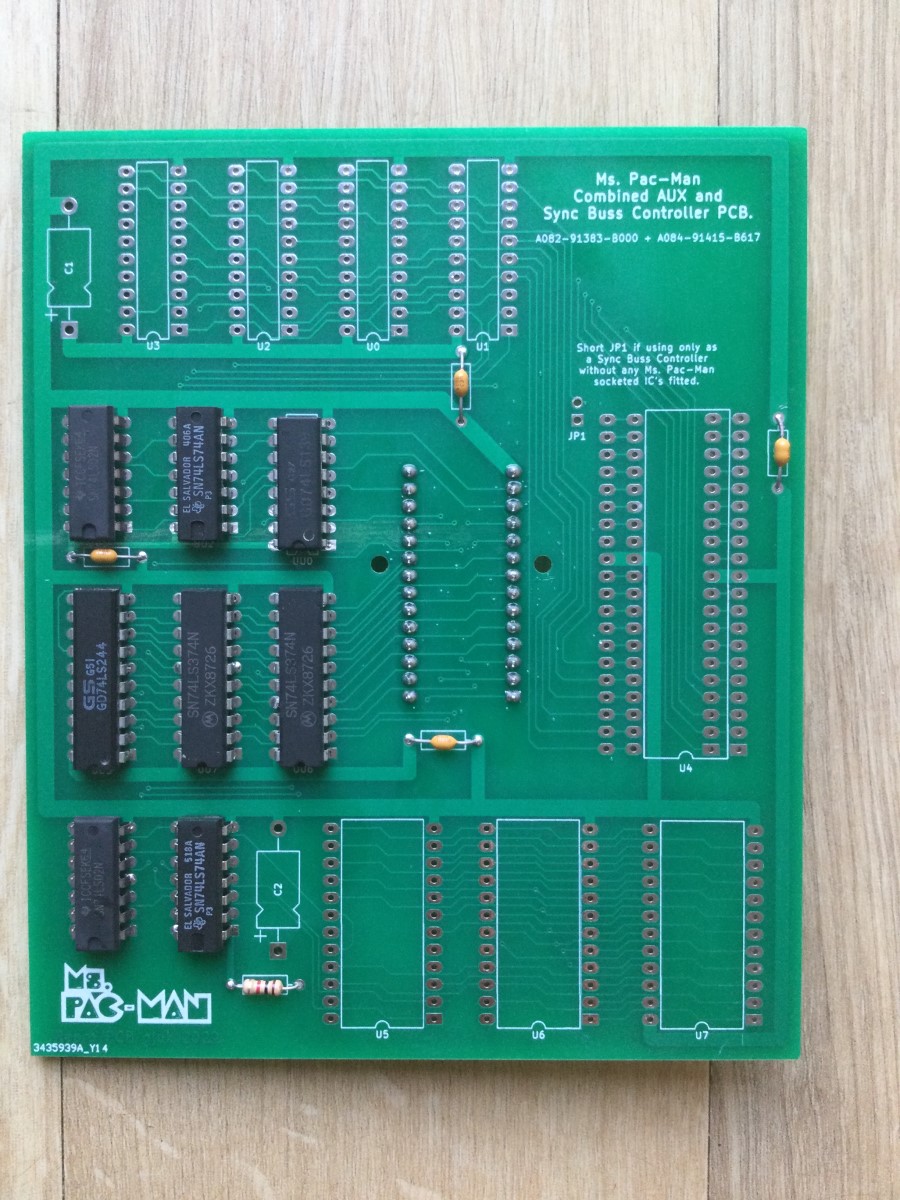
Another way to use it as just a Sync Buss Controller is to also solder in the Z80 socket and the pins for socket 6B (so the Z80 is running on the repro pcb and not the main Pac Man board) and jumper across JP1 and leave all the MS Pac Man chips out. This second method means the repro board is fitted more securely as it’s using both 6B and 6D sockets…

Here is a picture underneath the board. I originally made a slight boo-boo and forgot to connect pin 15 of U1 (the A7 address line) and the game kept re-booting. I realised my mistake after I had the boards made and a simple jumper wire solved the issue!...

I’ve now updated the Gerber files for this so any future produced boards won’t need the small modification!
Here's a full picture of the Pac Man board with the repro PCB fitted. It works a treat


The attached zip file contains the Gerbers should you wish to make one of these pcbs for yourself")
Pictured below is the official upgrade AUX pcb board that is needed to upgrade an original pcb to MS Pac Man. It’s a simple conversion that involves removing the Z80 from the Pac Man board, plug in the 40 pin cable going to the AUX pcb into the original Z80 socket at 6B, re-fit the removed Z80 processor onto the AUX board and replace the 2 Pac Man graphic roms at 5E and 5F on the original Pac Man pcb with MS Pac Man eproms.
The problem here is usually the 40 pin cable connecting between the Pac Man board and the AUX pcb. The cable is prone to failure, usually breaking at some point especially near the connector pins. Other issues are sometimes the sockets on the AUX pcb, they are the typical sockets Midway used and connection isn’t always great. There’s the further issue that because the AUX is an add on pcb connected via a cable, it needs to be secured somewhere to stop it from dangling loose. An original metal bracket was made for these to be mounted inside the wall of a cabinet but they are often missing nowadays.
Now I know you can modify an original Pac Man pcb to do away with the AUX board. However, this involves soldering in extra sockets, adding wires and cutting tracks etc., plus the replacement MS Pac Man roms required to make it work are actually bootleg roms. I like to keep everything original if I can so I wanted to create a simple plug-in solution that involves no soldering or hacking on the original Pac Man board.
Here’s what I’ve come up with…
My own reproduction pcb is a combined Sync Buss controller and AUX pcb in one. It plugs into both the Sync Buss socket at 6D and the Z80 socket at 6B. It’s basically the two separate schematics of the Sync Buss and AUX board re-arranged onto one pcb. Since it has been created using the original schematics, it needs the original 4x CG820/CG821/CG822/CG823 MS Pac Man custom chips and the normal MS Pac game roms for it to work. The entire footprint of the repro pcb is actually smaller than an original AUX pcb. The two small holes on the repro board line up nicely with the original holes at 6D if you want to add a cable/zip tie for added stability.
You can even use it as just a standalone Sync Buss controller (to play just Pac Man) by either not soldering any of the MS Pac Man sockets nor the Z80 socket (and just solder the pins for the 28 pin socket at 6D)…
Another way to use it as just a Sync Buss Controller is to also solder in the Z80 socket and the pins for socket 6B (so the Z80 is running on the repro pcb and not the main Pac Man board) and jumper across JP1 and leave all the MS Pac Man chips out. This second method means the repro board is fitted more securely as it’s using both 6B and 6D sockets…
Here is a picture underneath the board. I originally made a slight boo-boo and forgot to connect pin 15 of U1 (the A7 address line) and the game kept re-booting. I realised my mistake after I had the boards made and a simple jumper wire solved the issue!...
I’ve now updated the Gerber files for this so any future produced boards won’t need the small modification!
Here's a full picture of the Pac Man board with the repro PCB fitted. It works a treat
The attached zip file contains the Gerbers should you wish to make one of these pcbs for yourself
Attachments
Last edited:

