Problem Nintendo PP-7B Power Supply - Fault

K1ngarth3r

Active member
Feedback
21 (100%)
Credits
830CR
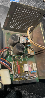
I have recently re-capped the power supply in my Donkey Kong cabinet, when I powered it on I heard a whine / whistle that increased in the loudness.

I thought I might have put a cap in the wrong location or orientation or maybe made a bridge since the caps are really close together on one of the boards, however after checking orientation, continuity, ESR reading of every cap everything seems to be good.

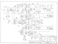
I plugged in the board labelled 3D-0097 alone and can recreate the issue there, so the problem exists at least here.

Does anyone have any idea what's going on, any advice on what to try next?

I have previously recapped one of these power supplies for Mario Bros cabinet and had no problems.

I'm on the verge of ordering a replacement PP-7B from the US (or putting a wanted add here incase anyone has one for sale). But thought it would be worth putting a help thread here, incase anyone's got some pointers (or maybe offer to fix it for me).
 

Attachments

  • IMG_5391.jpg
    IMG_5391.jpg
    178.3 KB · Views: 26
Last edited:

TheDaddy

Senior Member
vacBacker
Feedback
14 (93%)
Credits
7,019CR
Rule of thumb is if it was working fine before then you may have introduced the fault. There must be faulty parts, Bridged joints or faulty caps. Even though the ESR may work this does not always say the capacitor is ok (I have had blown capacitors when the ESR has been good when clearly the cap is wrecked). When I first started to read, Like you , i thought a cap inserted the wrong way as this will make them whine then explode, If the joints are all good I would replace the caps with a complete new set. That at least rules them out.

Dave.
 

K1ngarth3r

Active member
Feedback
21 (100%)
Credits
830CR
Well, I had removed all the capacitors and I get the following:

C30 = No Continuity but 102.9ohms resistance (Abnormal)
C18 = Continuity with 20ohms resistance (Normal)
C13 = No Continuity and 0ohms resistance (Normal)
C19 = Continuity with 20ohms resistance (Normal)
C31 = No Continuity but 103.0ohms resistance (Abnormal)
C37 = No Continuity and 0ohms resistance (Normal)
C20 = Continuity with 20ohms resistance (Normal)
C32 = No Continuity but 103.0ohms resistance (Abnormal)
C38 = No Continuity and 0ohms resistance (Normal)

This wasn't the case when I checked before, I think this has been made worse since then. I did install the original 330uf 200v caps into C6 and C7 to test earlier today.

I checked the resistors.

1685466960866.png

These were all tested in circuit.
 
Last edited:

TheDaddy

Senior Member
vacBacker
Feedback
14 (93%)
Credits
7,019CR
Strange , Once done try plugging it it on its own with nothing connected just in case there is a fault somewhere down the line and its just a coincidence maybe ? Also try resisters out of circuit as well.

Also when you say bad on Resisters I assume no contanuity at all or incorrect values ?

Dave.
 
Last edited:

K1ngarth3r

Active member
Feedback
21 (100%)
Credits
830CR
I'm not sure on the resistors, I need to work out what the correct value should be for each of the components I guess. For now, I've just added in the values.

In relation to the capacitors, I'm not sure why I'm getting 103 ohms resistance.
 

TheDaddy

Senior Member
vacBacker
Feedback
14 (93%)
Credits
7,019CR
I'm not sure on the resistors, I need to work out what the correct value should be for each of the components I guess. For now, I've just added in the values.

In relation to the capacitors, I'm not sure why I'm getting 103 ohms resistance.
Yeh it seems high. If you test it 5 times do you get the same result ?? Just to rule out tester. I would just start again with all new caps.

Dave.
 

K1ngarth3r

Active member
Feedback
21 (100%)
Credits
830CR
Schematics, you can see C30>C32 on the same circuit along with R27 which seems in spec.

Without any capacitors installed, I'm getting this on C30>32.
I just installed all new capacitors (47uf 50v x9), I just want to be sure the reading of 103 Ohms is normal on C30>C32 before powering it on.

When testing the board, I'm only sending the voltage from the cab to the single board only with no load.
 

Attachments

  • Screenshot 2023-05-30 at 17.24.45.png
    Screenshot 2023-05-30 at 17.24.45.png
    368.4 KB · Views: 17

K1ngarth3r

Active member
Feedback
21 (100%)
Credits
830CR
Updated my resistor chart, It seems the only one that seems majority off in circuit is R2.

Tested out of circuit and all okay 0.998
 
Last edited:

sukhbir

Active member
Feedback
45 (100%)
Credits
1,613CR
Possibly a cap is wrong way round, before removing electrolytic caps I always mark the tops which direction the positive is.

Sometimes manufacturers get the polarity printed wrong on the PCB.

Check the schematics to the caps you have replaced.
 

TheDaddy

Senior Member
vacBacker
Feedback
14 (93%)
Credits
7,019CR
Whats the value of C13 ?? In the old picture the cap looks much bigger than in recap image ?? I know some knew modern ones are differnt size with less voltage caps so you probably correct but just caught my eye. Not as using a different value would cause hissing like that unless the voltage was way lower than the input.

Also do you have a picture of solder side ?? Can have a look at that as well.

Dave.

P.S Polarity looks correct.
 

K1ngarth3r

Active member
Feedback
21 (100%)
Credits
830CR
All the nine capacitors on the right hand side are 45uf 50v, C13 on the schematics is actually 45uf 35v where as others (such as C18, C19 and C20 are 16v so all good.
The schematics are attached in a previous post I made.

I just recapped the board (the 9 caps and the same issue. My smart plug wasn't responding and it was left on for longer than I'd have liked and didn't get any worse. I'm wondering if the coil got wet and is damaged and that's the issue.
I will need to take the board out and take a photo.
 

TheDaddy

Senior Member
vacBacker
Feedback
14 (93%)
Credits
7,019CR
Ah sorry missed the diagram ! lol. Must be the huge magnum icecream I am slurping at same time.
Unsure where else to go with it now be honest.

Did you clean the board why it was out ?? If so how ?? (With you saying coil may be wet)

Dave.
 

TheDaddy

Senior Member
vacBacker
Feedback
14 (93%)
Credits
7,019CR
Not too sure , SOmeone like John Hughes may be able to direct you a little better on that. He is usually good with these sort of thing. The coil should give ohms but not sure how you test one to be fair and how to know what it should be.#

Dave.
 
Top