

In 1997 I bought a Rolling Thunder. It stopped at the boot stage.
I messed around a bit with bits of wire, shotgunned a few chips. No luck.

I even started looking for another voice PCB for some naïve reason:
https://groups.google.com/forum/#!search/rolling$20thunder$20bennett/rec.games.video.arcade.collecting/UJJLySM_ThY/QyBgonoDDh8J
(excuse the last line, I was a teenager - I think it was 'cos I'd seen places offering blank MCUs for £100).
I then bought another working copy and swapped every IC for a test - no luck.
So after that, it sat there in a cupboard for nearly 2 decades, bugging me slightly as the board that reminded me how crap I was at fixing stuff (while my little brother grew up and outdid me at all this stuff).
Anyway, about a year ago, armed with decent tools, I put the logic analyser on it and figured out that the main CPU was sat in a loop, kicking the watchdog and waiting for something.
So last week I finally looked a bit further and probed the slave CPU. That's waiting too.
I looked at the interrupt lines - all being cleared bar the main CPU. I had a play with the MAME debugger and that is correct at boot. I still suspected it was to do with sound, although didn't have the skills to prove it in MAME. The audio was making horrid noises whilst stuck at boot too.
I probed around and most things looked OK, but chief suspect was the 8B logic gate in the sound section.

The logic gates handle the link between the main CPU and the sound CPU, allowing access to shared RAM etc.
8B looked like this:
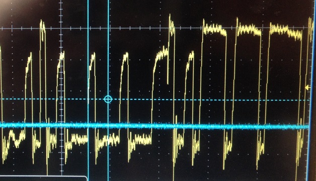
Barely over 3V with slow rise times.
One mistake was trying a 'helper' chip on-top. Did nothing and made me think it was OK - turned out the bad chip was dragging down the 'helper'. Always a dodgy trick anyway...
I spotted this very similar fix log by Caius (thanks!) and figured I should go with my instincts.
Swapped the IC:
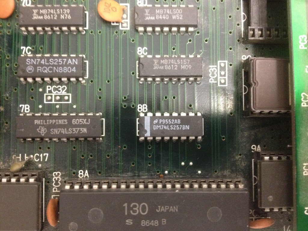
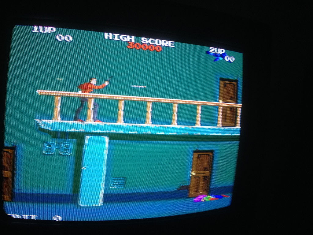
YAAY!
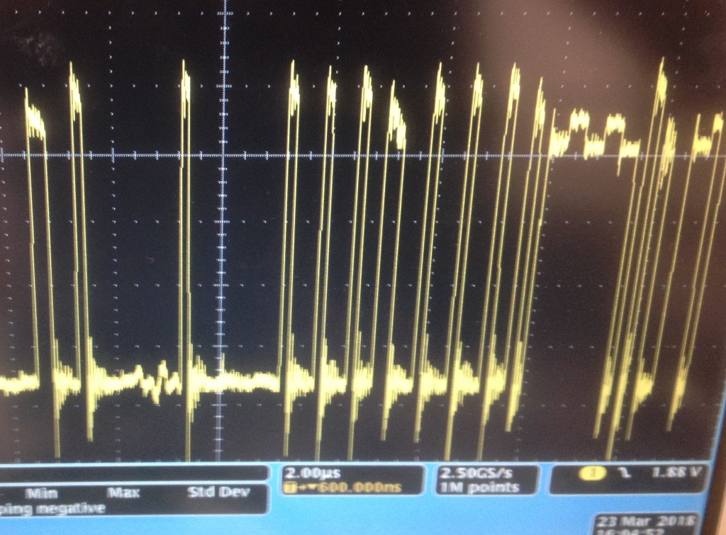
The output of 8B now (way over 4V):
I'm sure there are much more involved fixes, but in the case of this board, I'm rather chuffed with myself

P.S. The interrupt lines are quite interesting to watch - you can see the pulse duration go up as more is happening on screen. As it's effectively a PWM waveform, with a buffer you could have an LED for each processor that gets brighter with CPU loading
John Bennett2018-03-23 20:39:27
I messed around a bit with bits of wire, shotgunned a few chips. No luck.
I even started looking for another voice PCB for some naïve reason:
https://groups.google.com/forum/#!search/rolling$20thunder$20bennett/rec.games.video.arcade.collecting/UJJLySM_ThY/QyBgonoDDh8J
(excuse the last line, I was a teenager - I think it was 'cos I'd seen places offering blank MCUs for £100).
I then bought another working copy and swapped every IC for a test - no luck.
So after that, it sat there in a cupboard for nearly 2 decades, bugging me slightly as the board that reminded me how crap I was at fixing stuff (while my little brother grew up and outdid me at all this stuff).
Anyway, about a year ago, armed with decent tools, I put the logic analyser on it and figured out that the main CPU was sat in a loop, kicking the watchdog and waiting for something.
So last week I finally looked a bit further and probed the slave CPU. That's waiting too.
I looked at the interrupt lines - all being cleared bar the main CPU. I had a play with the MAME debugger and that is correct at boot. I still suspected it was to do with sound, although didn't have the skills to prove it in MAME. The audio was making horrid noises whilst stuck at boot too.
I probed around and most things looked OK, but chief suspect was the 8B logic gate in the sound section.
The logic gates handle the link between the main CPU and the sound CPU, allowing access to shared RAM etc.
8B looked like this:
Barely over 3V with slow rise times.
One mistake was trying a 'helper' chip on-top. Did nothing and made me think it was OK - turned out the bad chip was dragging down the 'helper'. Always a dodgy trick anyway...
I spotted this very similar fix log by Caius (thanks!) and figured I should go with my instincts.
Swapped the IC:
YAAY!
The output of 8B now (way over 4V):
I'm sure there are much more involved fixes, but in the case of this board, I'm rather chuffed with myself
P.S. The interrupt lines are quite interesting to watch - you can see the pulse duration go up as more is happening on screen. As it's effectively a PWM waveform, with a buffer you could have an LED for each processor that gets brighter with CPU loading
John Bennett2018-03-23 20:39:27


