Saving Doodle Jump!

myPinballs

Active member
Feedback
16 (100%)
Credits
681CR
First signs of life for the cabinet!
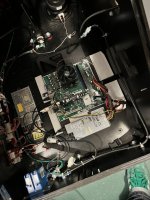
Main power supply was missing so sourced a new meanwell supply to same spec. 150w 12v

Unplugged the io board to test . Got a nice 12v and 5v output. There is a seperate 5v regulator board running off a Horizontally mounted 7805.

Plugged io board back in and got lots of nice leds lit up! Yellow flashing one which I assume means no data as I haven’t plugged the computer system in yet


89DEF9D6-063C-410D-8BAB-727F5F05DF71.jpegEDA8F325-57DC-4C49-A392-FDA2FDDC1792.jpegE11C1A46-D9AB-420A-AEC7-845430924502.jpeg
 

myPinballs

Active member
Feedback
16 (100%)
Credits
681CR
Some progress.

I was able to order a replacement dongle along with some other parts form sega total solutions. Decent service. I also got a new restore disc which is a later version, so will give this a go soon to. And a new plastic for the control panel toIMG_8721.JPGIMG_8723.jpgIMG_8739.JPGIMG_8740.JPGIMG_8720.JPG
 
Last edited:

myPinballs

Active member
Feedback
16 (100%)
Credits
681CR
And...

IMG_8730.JPG\\

First successful boot up. :)

There are loads of test options and setting to go through, but i need to assemble everything properly i think now and check all the i/o stuck. controls etc. Probably will use this monitor for testing, then i will get a proper 42" one. I have a lead on one with the correct resolution, May need some minor adjustment to fit, but is an oem lg one. Not for this cabinet but other arcade stuff i think.

The final step of the boot process after the dongle check is passed is a 'volume check' then it launches the game so i'll add that to the list of boot processes. Also on the first boot up with a new hard drive, it goes through and checks a load of assets, music/image files etc etc. Boot ups after that are much quicker.


IMG_8752.PNGIMG_8753.PNG
 

myPinballs

Active member
Feedback
16 (100%)
Credits
681CR
So the full boot up process is :

  1. - Boot into Prompt?
  2. - HDD Write Filter Check
  3. - HDD Integrity Check
  4. - Graphics Card Check
  5. - Monitor Resolution Check
  6. - RAM Check
  7. - I/O Board Initialisation (Windows WINUSB)
  8. - Parallel Port (LPT) Check
  9. - Security Dongle Check
  10. - Volume Check
  11. - Launching Game
 

myPinballs

Active member
Feedback
16 (100%)
Credits
681CR
What connection does it use for the monitor, if its DVI or HDMI I wonder if there is some way to spoof the supported resolutions IDs with a box sitting between them, so the PC thinks its the correctly supported monitor.

Possibly with something like this, but pricy though, but could be cheaper than a matching monitor. https://www.startech.com/en-gb/audio-video-products/vsediddvi
That more expensive than a monitor i have sourced at the correct resolution and size!
 

myPinballs

Active member
Feedback
16 (100%)
Credits
681CR
More progress

The hall effect sensor for the main joystick was missing/broken, so i ordered a replacement . The ground wire to the joystick was also bust so sorted that out to. Luckily both screws for the mounting of this small board were in the bottom of the cab , haha

IMG_8799.JPG
 

myPinballs

Active member
Feedback
16 (100%)
Credits
681CR
First test assembly of modified cab. This is just the internal plywood sides and monitor assembly supports. You can see my custom cutouts for the cabling. The idea if then to mount the other plywood sides wit ht he artwork on onto these sides, thus sandwiching the cables internally as before etc. For even more weight saving you could make thinner outer sides with new artwork on etc, but i am using the original pieces for now.

IMG_8805.JPGIMG_8807.JPGIMG_8808.JPGIMG_8809.JPGIMG_8810.JPG
 

myPinballs

Active member
Feedback
16 (100%)
Credits
681CR
Main game control button assembly. Ordered all new buttons and microswitches for this. All of them were flaky and bent. These std suzo buttons dont last too well. Also the mystery of the random cable found in the bottom of the cab was identified as the power cable for this centre led pcb. Must have broken off at some point. This lights up in red i believe.


IMG_8812.JPG
 

myPinballs

Active member
Feedback
16 (100%)
Credits
681CR
Updates - Addressing the led strip on the main monitor panel

Some of the led strip light for the border on the lcd panel was loose and coming away, plus the rubber strip padding for the glass screen was all cracked and degraded so i removed this to replace and reattached all the led strips

IMG_8820.JPGIMG_8821.JPGIMG_8822.JPGIMG_8823.JPGIMG_8824.JPGIMG_8825.JPGIMG_8826.JPGIMG_8827.JPGIMG_8828.JPGIMG_8829.JPG
 

myPinballs

Active member
Feedback
16 (100%)
Credits
681CR
Thought i was home and dry on the control panel area, until this .... :mad: Slot is not large enough on the CPO for the joystick top diameter.. New plastic panel artwork look great though

So i am faced with a problem as to what to do. I think i've got to make a larger hole somewhere on this curve, not happy when its an official item

Thoughts welcome !!

IMG_8938 3.jpgIMG_8953.JPGIMG_8954.JPG
 

myPinballs

Active member
Feedback
16 (100%)
Credits
681CR
some new updates on this long term project!

LCD Screen info and updates!

- managed to source a nice LG/Philips 1366x768 native resolution monitor 42" size. Actually bought 2 as it was a decent ish deal. So i have a spare for another sad doodle jump!
- Modification with the router of the white nylon bezel was needed to mount it as the screen was about 25mm longer than the original wg one.
- Also had a job working out what control boards to hook up to this LVDs port but think that is now sorted.
- Needs 12v and 24v power inputs. The 24v is for the backlight, which i need to make some wiring additions for

rear backboard with bezel removed

IMG_3545 2.JPG

Machining bezel/surround

IMG_3549 2.JPGIMG_3552 2.JPGIMG_3555 2.JPG

Monitor

IMG_3546 2.JPGIMG_3547 2.JPG

Installed

IMG_3574 2.JPGIMG_3575 2.JPG
 

myPinballs

Active member
Feedback
16 (100%)
Credits
681CR
Update, monitor is now working. What a job this was. More details to follow on what was needed, but its was complex along with 2 power supplies needed and much custom wiring aswell as a special control board. Know alot more about 42" lcd screens now to!!

Some pics

Screen lit up

IMG_3810.JPG
IMG_3808.JPGIMG_3809.JPGIMG_3813.JPGIMG_3815.JPG

Driver Hardware & wiring pics

IMG_3802.JPG
IMG_3803.JPGIMG_3804.JPGIMG_3805.JPG
 

Attachments

  • IMG_3807.JPG
    IMG_3807.JPG
    114.4 KB · Views: 9

myPinballs

Active member
Feedback
16 (100%)
Credits
681CR
So some more tech details on the monitor setup. Picture is really crisp and bright. Great contrast. (Screen model is LC420W02. I actually have a second one if anyone else wants to do this to a broken doodle jump.)

Firstly the monitor is a 42" LCD with CFL backlight (fluorescent). It needs 2 voltages 12v and 24v. 12v is for the digital side and 24v is for the backlight side.
The control side i sorted by speaking with one of the chinese lcd adapter manufacturers. It took alittle time to find someone who understood what hardware was needed for these larger screens and the connector types required (30 pin LDVS, 8bit, 1 channel in this case)

The backlight side has 2 power connectors and 2 signal wires. The connectors were JST 2.0mm connectors so this also took awhile to fathom out and that both connectors are needed. Originally i thought only 1 was needed as the slave side is power only and no signal wires.

I also connected both grounds for the 2 power supplies because the signal control 2 wires (backlight on/off and backlight brightness level) come form signals generated off the controller board. 5v and 0v for on /off and 0-3.3v of the backlight brightness, which is controlled via the digital controller adjustments.

IMG_3803 2.JPG

IMG_3789.JPG
IMG_3788.JPG
 
Top