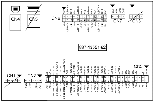
Trying to make a analog loom
Really hope this makes sense as it’s confusing me trying to write it!
Got the analog sticks with the original 4 way amp up connector terminal.
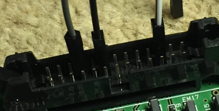
I have just wired it to the pins with arduino jumpers just to test . - Sus it out - I get up and down
But that’s it.. in the test mode in monkey ball.
I have been reading and I found that it also needs calibrating After this test page.
But I can go to jvs test mode screen
But I cannot go to the next node?
Yes It says next node?
So is this NEXT NODE the area where you calibrate the sticks?
And can I not go there because I have not yet wired my connectons in the right order and. Nor have I wired it completely as confused as to what the vcc is?
Confused as 6 wires from the stick

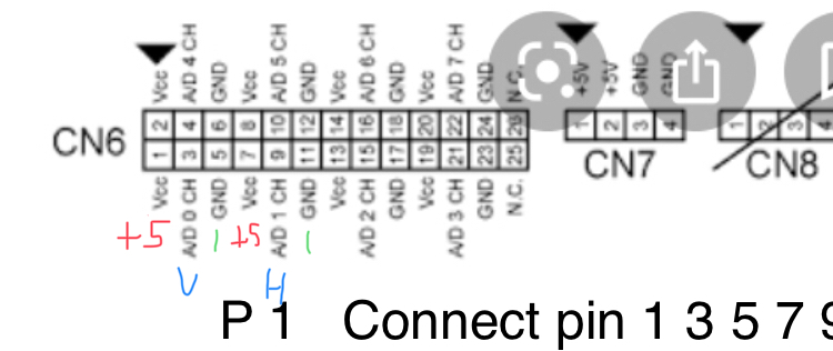
But looks like I need 8 connections..
Acc. Is I think volts +5? But Where do I need to jumper this from?
First Pic above best I have managed is the three wires connected I get up and down in test mode..
But can’t get the left and right..
And I think this is why I cannot access the calibration screen?
Any Help most appreciated
Retroman8392021-01-11 21:50:39
Really hope this makes sense as it’s confusing me trying to write it!
Got the analog sticks with the original 4 way amp up connector terminal.
I have just wired it to the pins with arduino jumpers just to test . - Sus it out - I get up and down
But that’s it.. in the test mode in monkey ball.
I have been reading and I found that it also needs calibrating After this test page.
But I can go to jvs test mode screen
But I cannot go to the next node?
Yes It says next node?
So is this NEXT NODE the area where you calibrate the sticks?
And can I not go there because I have not yet wired my connectons in the right order and. Nor have I wired it completely as confused as to what the vcc is?
Confused as 6 wires from the stick
But looks like I need 8 connections..
Acc. Is I think volts +5? But Where do I need to jumper this from?
First Pic above best I have managed is the three wires connected I get up and down in test mode..
But can’t get the left and right..
And I think this is why I cannot access the calibration screen?
Any Help most appreciated
Retroman8392021-01-11 21:50:39