
You are using an out of date browser. It may not display this or other websites correctly.
You should upgrade or use an alternative browser.
You should upgrade or use an alternative browser.
System 1 Atari ,how to power amp from switcher ?
- Thread starter Body pop
- Start date


ah still the same .its not liking somethingView attachment 66053
According to this Red - 12V AC Low Violet 12V AC Hi and Orange 18V AC.
So with this new transformer these are no longer connected? If that's correct you need to connect Violet to +12v on the switcher and red to ground.
You might need to connect Orange to +12v on the switcher too, not sure if this is needed, there's another diagram that shows it does go to the amp though.
View attachment 66054
The red 12v low ,definitely to ground ?
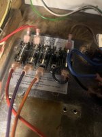

I’ve just traced the orange wire from the connector going to the audio 2 boardIs it connected to a test point? looks like it has been messed with and not factory. There's no orange wire on the amp connector?
It goes over into the game boards ,same connector ,same hole as that other orange
Is it some kind of loop in and out maybe ?
Attachments
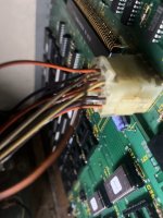


Measuring at the connector the orange is getting 0
The red pin second down is showing 13v without load
Atm that orange wire. the 18v that was on transformer previously is only gong to one side of a fuse block with nothing in other side of fuse
From the 12 v on the switcher
It’s not connecting up with anything
The red pin second down is showing 13v without load
Atm that orange wire. the 18v that was on transformer previously is only gong to one side of a fuse block with nothing in other side of fuse
From the 12 v on the switcher
It’s not connecting up with anything
Attachments

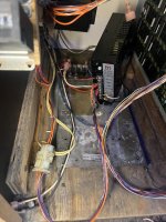
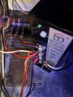
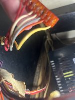
Thanks for your patience
That orange wire goes straight to the game pcb block connector
Where there is 2nd orange wire coming out of exact same point on same connector .
The lose wire is coming out and going nowhere
If I send the 12v to that lose wire from switcher
Would that supply the main board and the audio board the 12v
As that would be a loop of orange wires
Into pcb and out to audio board
Or should I remove the orange wires from pcb ,so that the 12v is only going to that audio board ,directly from the switcher .
Not to pcb
That orange wire goes straight to the game pcb block connector
Where there is 2nd orange wire coming out of exact same point on same connector .
The lose wire is coming out and going nowhere
If I send the 12v to that lose wire from switcher
Would that supply the main board and the audio board the 12v
As that would be a loop of orange wires
Into pcb and out to audio board
Or should I remove the orange wires from pcb ,so that the 12v is only going to that audio board ,directly from the switcher .
Not to pcb
It's hard to tell what's going on what's not connected, but the game pcb is already getting 12v so that's fine, you need to focus on getting 12v into the orange wire in the picture above that goes to the amp.
Just don't connect the 12vac from the old transformer if it's still installed to the switchers 12v, as it'll kill the switcher.
Continuity / beep test on your multi meter will tell you if the above orange wire goes where you think it does if you cannot see exactly where it's going.
Just don't connect the 12vac from the old transformer if it's still installed to the switchers 12v, as it'll kill the switcher.
Continuity / beep test on your multi meter will tell you if the above orange wire goes where you think it does if you cannot see exactly where it's going.