

Bought this Taito Phoenix a while back and decided to attempt to fix it. Sounds were missing from the game.
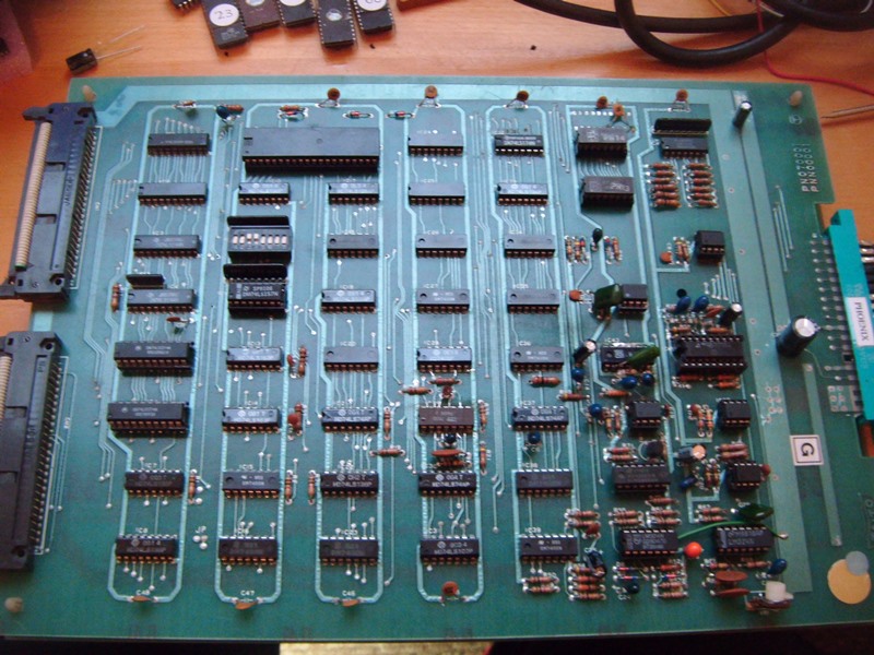
The sound section had been heavily shot-gunned before it came into my possession. Almost every component relating to the sound section had been pulled and replaced but the problem persisted. Turned out that the resistor at R47 had sheared in two. Replaced the resistor and the sounds were, thankfully, restored. Don't have a photo, but the resistor can just be seen in the stock photo.

Replaced resistor.
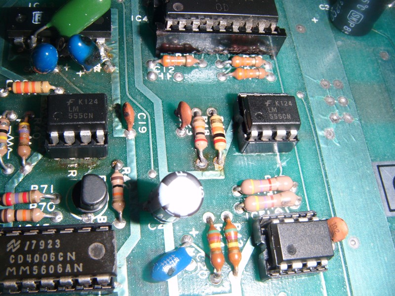
Game seemed to be fixed, had a few games and all was well. However, out of curiosity started a two player game and when two player started the sprites were wrong with letters in them on the diving birds and the ship was stuck at the top of the screen. This only happened for player two.
Player 1:

Player 2:

Game couldn't progress in player 2 mode, ship could not be hit
Problem turned out to be the 2114 at IC44.

Replaced the 2114 chip and now I have a very nice working Taito Phoenix PCB.

The sound section had been heavily shot-gunned before it came into my possession. Almost every component relating to the sound section had been pulled and replaced but the problem persisted. Turned out that the resistor at R47 had sheared in two. Replaced the resistor and the sounds were, thankfully, restored. Don't have a photo, but the resistor can just be seen in the stock photo.
Replaced resistor.
Game seemed to be fixed, had a few games and all was well. However, out of curiosity started a two player game and when two player started the sprites were wrong with letters in them on the diving birds and the ship was stuck at the top of the screen. This only happened for player two.
Player 1:
Player 2:
Game couldn't progress in player 2 mode, ship could not be hit
Problem turned out to be the 2114 at IC44.
Replaced the 2114 chip and now I have a very nice working Taito Phoenix PCB.


