

I'm servicing a Wiliams PSU board, working but the connectors had previously been hacked about and needed changing. Unfortunately when removing the header pins some of the pads came loose and floated off the board, this log is about repairing this rather than the rest of the PSU. I don't have the 'proper' tools to do this - there are kits available but they can be expensive.
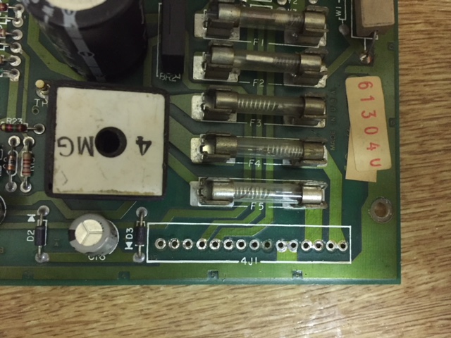
So this is the 15pin connector after removal, several pads are gone. actually the through hole is still present but still not much to solder to. It seems to be mainly the ones where the track is on the top of the board or not connected.

On top, only one gone.
These are the tools I used...

The most important bit here is the replacement through holes, if you search on ebay for 'through hole rivets' you'll find them for a few quid. I had some already from a pinball driver board repair, they were 2mm x 4mm, they were a bit long hence the selection of files to shorten them about 1-1.5mm.
Drill for clearing out the hole. This wants to be just the right size so the rivet is snug in the hole.
Hammer, centre punch and a lump of metal (as an anvil) for setting the rivet.
Vernier caliper to measure things.
So first step is to drill out the hole, try not to damage what's left of the pad and track on top. I found drilling from the opposite side to where the track goes away from the hole better. Then insert the rivet

You want about 0.5-1mm of rivet out of the back of the board, you may have to shorten it and also shape the head a little if it's a bit close to the one next to it.
Then flip the board over, place the anvil under the rivet head the punch on the back tap it to splay it out. You can then tap it with the hammer to flatten it out.

This one split a little as it was a little too long, it's still ok though. I got a bit better as I went along

And on top

Then repeat the process for all the holes. I got a bit on a roll here and didn't take so many pics
But when you're done flow a bit of solder around the hole where there is a track.
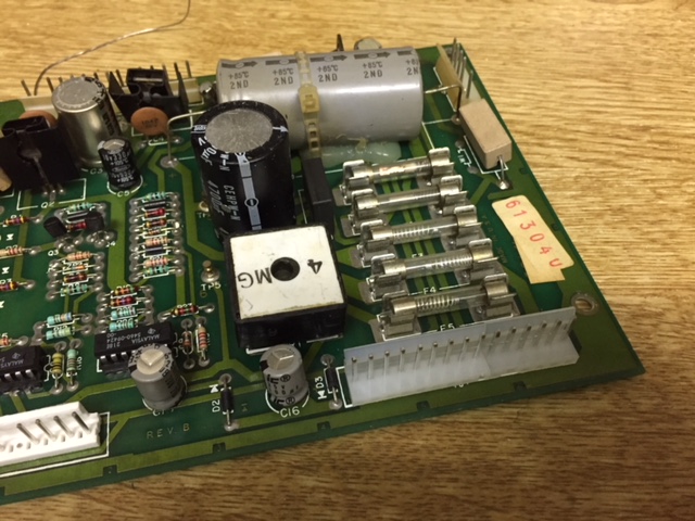
Finished repair

Final thoughts:
This would have been much harder if the holes weren't on the edge, my anvil would have been no good.
I expect this would be a lot harder given smaller holes!
Overall i'm pretty pleased with the repair, much neater and stronger than running patch wires.
So this is the 15pin connector after removal, several pads are gone. actually the through hole is still present but still not much to solder to. It seems to be mainly the ones where the track is on the top of the board or not connected.
On top, only one gone.
These are the tools I used...
The most important bit here is the replacement through holes, if you search on ebay for 'through hole rivets' you'll find them for a few quid. I had some already from a pinball driver board repair, they were 2mm x 4mm, they were a bit long hence the selection of files to shorten them about 1-1.5mm.
Drill for clearing out the hole. This wants to be just the right size so the rivet is snug in the hole.
Hammer, centre punch and a lump of metal (as an anvil) for setting the rivet.
Vernier caliper to measure things.
So first step is to drill out the hole, try not to damage what's left of the pad and track on top. I found drilling from the opposite side to where the track goes away from the hole better. Then insert the rivet
You want about 0.5-1mm of rivet out of the back of the board, you may have to shorten it and also shape the head a little if it's a bit close to the one next to it.
Then flip the board over, place the anvil under the rivet head the punch on the back tap it to splay it out. You can then tap it with the hammer to flatten it out.
This one split a little as it was a little too long, it's still ok though. I got a bit better as I went along
And on top
Then repeat the process for all the holes. I got a bit on a roll here and didn't take so many pics
But when you're done flow a bit of solder around the hole where there is a track.
Finished repair
Final thoughts:
This would have been much harder if the holes weren't on the edge, my anvil would have been no good.
I expect this would be a lot harder given smaller holes!
Overall i'm pretty pleased with the repair, much neater and stronger than running patch wires.
