Time Pilot repair/refurb/resurrect

patzik

Active member
Feedback
1 (100%)
Credits
373CR
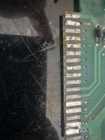
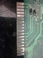
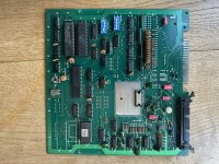
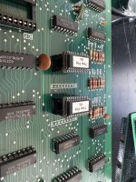
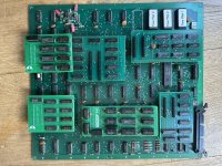
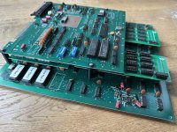
In the pile of incomplete/non working PCB’s I have a Time Pilot that I decided to give some attention. Here’s some pictures.
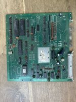
IMG_4519.jpegIMG_4518.jpeg
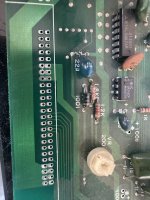
As you can see the top board is missing the dipswitches, has a pretty bad edge connector and the connector For the ribbon cable has some odd size. The ribbon cable is missing and none of the ribbon cables I have fit. The bottom board is missing all roms and 2 proms, and 3 of the custom replacement PCB’s are missing.
Basically this would normally be a write off but for fun I decided to bring this one back. I also have a complete one, so this will help with those customs.
 

patzik

Active member
Feedback
1 (100%)
Credits
373CR
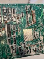
Starting with the top pcb, first it needs a good wash
.IMG_4530.jpeg
Then onto the edge connector, excess solder removed and cleaned up.
IMG_4521.jpegIMG_4520.jpegIMG_4524.jpegIMG_4522.jpeg
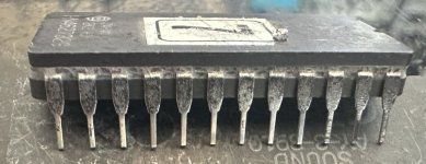
Before washing a removed the rom and this also deserved some attention on the corroded legs.
IMG_4525.jpegIMG_4526.jpeg
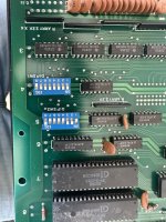
Dipswitches replaced
IMG_4532.jpeg
Ribbon connector removed so a new one can be fitted.
IMG_4529.jpeg
 
Last edited:

patzik

Active member
Feedback
1 (100%)
Credits
373CR
The top board had some crusty looking caps, of which one was broken off/lost its leg. So decided to replace all caps for fresh and new. Also salvaged a ribbon cable connector for it. So the top board is doneIMG_4544.jpeg
 

patzik

Active member
Feedback
1 (100%)
Credits
373CR
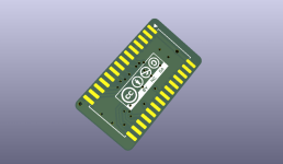
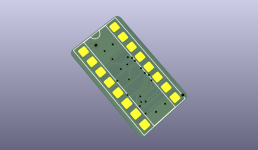
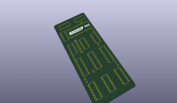
On to the bottom board, as said this was missing the roms, so I burned a set of 6 27C64 eproms. It was also missing the 2 color proms, these are 82s123 proms for which I have made an adapter in the past. As these adapters use 27c512 eproms they are quite bulky so I have designed a new adapter for these proms. The adapter uses an smd 28c64 eprom, and the legs get soldered directly to the bottom side without any holes so making these takes a little bit of effort. I use precision header and snip off the small bits that normally go through the pcb and then solder it to the pcb. The 28c64 eprom is programmed before soldering it to the pcb.
1791466814026.png1791466855072.png
This is the result.
IMG_4542.jpegIMG_4540.jpeg
 

sukhbir

Active member
Feedback
46 (100%)
Credits
1,681CR
On to the bottom board, as said this was missing the roms, so I burned a set of 6 27C64 eproms. It was also missing the 2 color proms, these are 82s123 proms for which I have made an adapter in the past. As these adapters use 27c512 eproms they are quite bulky so I have designed a new adapter for these proms. The adapter uses an smd 28c64 eprom, and the legs get soldered directly to the bottom side without any holes so making these takes a little bit of effort. I use precision header and snip off the small bits that normally go through the pcb and then solder it to the pcb. The 28c64 eprom is programmed before soldering it to the pcb.
View attachment 66367View attachment 66368
This is the result.
View attachment 66369View attachment 66370
Nice bipolar prom adapter,by the way what is the speed of the 28c64 soic eprom?
usually these have to be in the range of 50-60ns To work properly.
 

patzik

Active member
Feedback
1 (100%)
Credits
373CR
Nice bipolar prom adapter,by the way what is the speed of the 28c64 soic eprom?
usually these have to be in the range of 50-60ns To work properly.
They are 150ns, so I’m not sure if they will work yet. There is enough space I think to use the bigger adapters but I wanted to try these out. I have come across several PCB’s where there was not enough room for the bigger adapters so that’s how I came to this design. I have also made the 82s126/129 version and when all is tested I will make things public, I am looking into making a GitHub for this kind of stuff.
 

sukhbir

Active member
Feedback
46 (100%)
Credits
1,681CR
They are 150ns, so I’m not sure if they will work yet. There is enough space I think to use the bigger adapters but I wanted to try these out. I have come across several PCB’s where there was not enough room for the bigger adapters so that’s how I came to this design. I have also made the 82s126/129 version and when all is tested I will make things public, I am looking into making a GitHub for this kind of stuff.
Nice,good luck :)(y)
 

patzik

Active member
Feedback
1 (100%)
Credits
373CR
The custom replacement pcb's have been built. The 083 worked right away, but the 502 didn't (there were lines one the screen). After some time probing the signals and using a video probe to see where the video generation went wrong, I found one error where I had a pin 1 connected wrong. I fixed this with a bodge wire and the video became better but still some glitches. These glitches turned out to be the 74ls244 I used. Still don't fully understand why, but the 244 generated good signal on one side but glitched signals on the other side. The 244 itself tested good, so I tried a 244 from the same brand and same result. A 244 form others brands however worked fine. The 244's were all salvaged from donor pcb's so they are original and not some fake chines hc chip. Can't explain it but it works now.
I am happy to say that the 82s123 color replacement proms also work great so the 150ns is good enough for this use.IMG_4543.jpeg
 

patzik

Active member
Feedback
1 (100%)
Credits
373CR
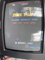
To my surprise, with the newly placed roms, proms and 3 customs the pcb full works, so no repair needed. I expected this pcb to be put aside broken and then used for parts but turns out it was fully working when the parts were robbed...
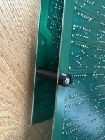
The standoff's were missing and the holes in the pcb are a bit too big for the 'normal' m3 screws so I think it deserves some nice custom pcb standoff's
Screenshot 2026-10-11 at 12.36.47.pngIMG_4549.jpegIMG_4550.jpeg
 
Last edited:
Top