Vector Arcade Machine - Pre Flight Checks

edwoodjnr

Active member
vacBacker
Feedback
2 (100%)
Credits
243CR
This is a repost from J+ that I posted in 2012 after getting my Star
Wars, hopefully it will useful for any new Star Wars owners who want to run through
some checks before switching it on or if you have problems.

I am not an expert and a big thank you goes to ColinD for all the help and patience in helping me
with this. There is a lot of very good information available on the
internet that explains the sections covered in this guide in a lot more detail
that I will refer to but hopefully you will find it useful.

The
first thing to do is to purchase a Multimeter that has a diode setting and
ideally an audible continuity test. I got this one (GW24B) from
Maplin for £19.99 that works very well:
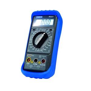
gw24_side.jpg


http://www.maplin.co.uk/digital-multimeter-with-autorange-frequency-counter-4407

For most usage you will insert the black lead in the COM socket and the
red lead in the V?mA socket. The dial in the middle is used to
amend the sensitivity of the Multimeter and should be set to the next highest
setting of what you are measuring. So if you are testing for 37v DC you
would need to set the switch to DC and the dial to 200. If you are
testing 12v DC you would turn the dial to 20.

For this guide I will be using a Star Wars Upright cabinet with a WG6100
monitor that was sold as not working. As it is an Atari classic it
has the following four key segments that enable gameplay:

- Atari Power Brick = Transformer / Fuse carriers / Bridge Rectifier /
Big Blue Capacitor and also mains and other connectors

- Audio Regulator PCB (AR2) = Various Voltage sections (where fitted)
and amplifiers (where fitted

- Game board PCB = CPU board , AVG board and Sound board

- Monitor = High Voltage PSU, deflection PCB
(Low Voltage rails, X and Y amplifiers, Spot Killer), and the tube itself

For each of these items I recommend downloading the service manuals as it will
help you figure out which voltages need to be checked. You
can get them here:

http://www.vernimark.com/arcade/default.asp?PageMode=9

http://arcarc.xmission.com/

Now that we have identified the items we are going to check we will first begin
with checking the fuses on the Power Brick and deflection PCB.
 

edwoodjnr

Active member
vacBacker
Feedback
2 (100%)
Credits
243CR
Check the fuses

Using the continuity setting on the multimeter,
locate the fuses on the power brick and connect the leads to both ends of the
fuses, or better fuse holders. If the fuse is ok you should hear a beep.
One of mine was gone which was easy to replace.

On the power brick there are 6 fuses:

F2 – 4a

F3 – 20a

F4 thru F6 – 4a

F1 – 7a (located in the black terminal,
twist to remove)

If one of the fuses is bad you can find replacements here:

http://uk.farnell.com/littelfuse/0313004-hxp/fuse-cartridge-4a-6-3x32mm-slow/dp/1149720
http://uk.farnell.com/littelfuse/0313007-hxp/fuse-cartridge-7a-6-3x32mm-slow/dp/1149722
http://uk.farnell.com/littelfuse/0313020-hxp/fuse-cartridge-20a-6-3x32mm-slo/dp/1149735

On the deflection PCB there are 4 fuses that should also be checked.
Next, power brick voltages.
 

edwoodjnr

Active member
vacBacker
Feedback
2 (100%)
Credits
243CR
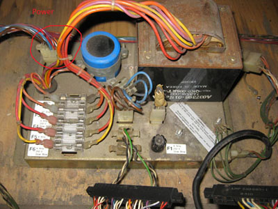
Power Brick Voltages

Disconnect
the plug that goes to the monitor and the game PCB connector for this
test. Next unplug the plug that is circled on this picture and
connect the power.

400powerbrick.jpg


You will need to meter the voltages on the DC and AC pins as explained
in this YouTube video.

http://www.youtube.com/watch?v=C1pVTzEF3ZA

Here are my readings, remember these are unloaded
so will be a little higher:


Power Brick DC


Red


Black


Expected


Actual


1


4


10.5v


14.94


2


4


10.5v


14.94


3


4


10.5v


14.94


If no voltages on pin 1 then check the fuses

Change the Multimeter setting to AC for these
tests:


Power Brick AC


Red


Black


Expected


Actual


6


7


37.5v


38.1


8


9


6v


6.66


10


13


50v


53.2


11


13


25v


26.4


edwoodjnr

Active member
vacBacker
Feedback
2 (100%)
Credits
243CR
Check the voltages on the AR2 (+sense mod)

There are divided opinions on whether
or not to apply the sense mod to the AR2. There is a very good guide here
on how to apply this mod to your AR2.

http://www.stickycarpet.com/pinx/ar2mods.htmlhttp://www.stickycarpet.com/pinx/ar2mods.html


It seemed straight forward and I
applied the mod to my AR2. With the sense mod fitted, unplug
J7 and J10 plugs on the AR2 – these will be marked on the PCB. Next, put
the power plug put back into the power brick and keep the game board connectors
and monitor unplugged. All other plugs can be connected.

With the power on you should be able to look at the
ARII voltages (unloaded) at J7 and J10. Refer to the AR2
schematics diagram on page 4 here:

http://arcarc.xmission.com/PDF_Arcade_Atari_Kee/Star_Wars/Star_Wars_SP-225_2nd_Printing.pdf

Note, on the diagram for J7, the pins 1
and 4 are ground for the black probe lead. You can now probe the other
pins with the red probe lead.

Here are my readings:


ARII Voltages


Red


Black


Expected


Actual


J7


5


1


5v


5.23


6


1


5v


5.23


3


1


5v


5.23


2


1


0v


0


J10


4


12


12v


11.93


1


12


22v


25.3


2


12


22v


25.3


3


12


-22v


-25.2


6


12


-22v


-25.2


7


12


+15v


0


10


12


-15v


0


9


12


-5v


-7.08


Note, for the J10 plug, the diagram has
a dotted line around 7, 10 and 9 so it may not be fitted to the board.

With the 5v sense fitted you could then adjust R8 (the pot) to give
about 5.1 to 5.2 volts. When it gets to the game board, it will drop a
little so you will get 5.0 to 5.1 volts. To test this on the game
board reconnect the PCB and meter the test points.

edwoodjnr2014-09-04 19:52:19
 

edwoodjnr

Active member
vacBacker
Feedback
2 (100%)
Credits
243CR
Check the Chassis Transistors.

For this test you will need to set your multimeter
to the diode setting. It looks like an arrow with a vertical line at the
end -->|-

A Diode looks like this.....

1 -----I<I----- 2

If you place the red lead on the right
side 2 and the black lead on the left side 1, you should read something like
0.6 > 0.8 that shows the voltage drop across the diode. If
you reverse the leads you won’t get anything.

The Chassis transistors have both NPN
and PNP transistors. NPN transistors look like this but they have 3
leads:

1(c)-----I<I------2(b)-----I>I-----
1(e)

C = collector , B = Base, E = Emitter.

For checking the Chassis transistors
the power should be off and you need to meter them at the plug end,
unplugged. i.e. not connected to the deflection PCB. 1 plug = two
transistors = 6 wires.

Place your leads as before, red on 2
and black on 1 and you should get 0.6v. Move the black to the other
1 and you should read the same. Reverse the Leads and you should not get
anything and for an extra sanity check also measure 1c to 1e both
way and it should be open.

PNP Transistors are the same but the diodes point inwards instead of
outwards so same thing again, but reversed 1c to 1e should be
open both ways. If you look at the y-amplifier on the deflection
PCB in the WG6100 manual the chassis transistors are shown as:

600yamp.jpg


Although the y-amplifier is shown in
the diagram, the x circuit is the same which means that the same tests can be
applied for the x, y and power regulation circuits. These are connected
to the P700, P600 and P100 plugs on the deflection PCB.

Remember to check the transistors on the plug end, unplugged. I
have removed the deflection PCB so you can see it better. The red wire
going to the plug is pin 1.

400chassistrans.jpg


350delectionpcb.jpg


Here are my readings:


Red


Black


P100


P700


P600


NPN Tests


1


Chassis


1


3


1


4


3


Chassis


3


1


0.577


0.526


0.573


3


4


0.581


0.528


0.574


4


Chassis


4


1


4


3


PNP Tests


5


Chassis


5


6


0.59


0.589


0.594


5


7


6


Chassis


6


5


6


7


7


Chassis


7


5


7


6


0.582


0.583


0.591


edwoodjnr

Active member
vacBacker
Feedback
2 (100%)
Credits
243CR
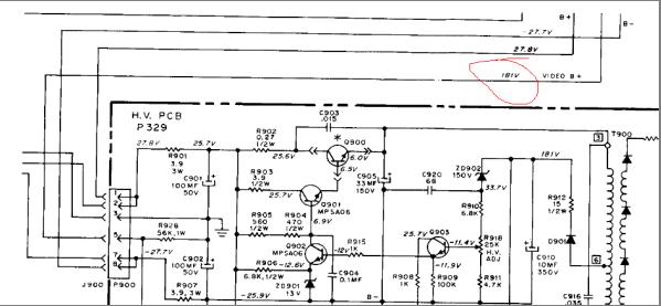
Check the high voltages.

For this test leave the game PCB disconnected but connect the monitor
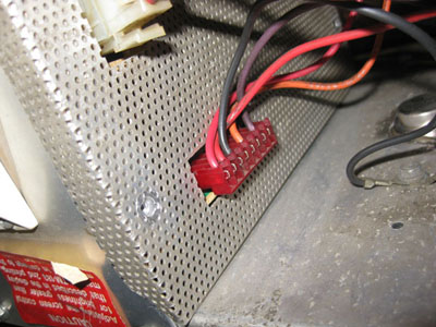
plug. On the 8 pin connector on the HV PSU, put the black probe on
pin 3 and check the voltages on pins 1, 2 , 5 and 7. For this monitor the
schematic diagram shows the expected voltages.

It shows that on pin 5 I should get 181v.

hv_pcb.jpg


400hvpcb.jpg


Unfortunately I didn’t have this
voltage which points to a problem with the HV PCB. Pin 1 is the red one
shown in the picture.

Here are my readings:


HV Voltages


Red


Black


Expected


Actual


1


3


27.5v


28.9


2


3


27.5v


28.8


5


3


181v


27.3


7


3


-27.5v


-28.4


Please add to this thread with any
further useful tips.
 

ColinD

Active member
Feedback
6 (86%)
Credits
1,367CR
Nice work.... I enjoyed working with you on that as you didn't jump the gun and start mucking about else where.

The Notes above refer to the WG6100 monitor , but the power brick and ar2 are the same of course if you have an amplifone in there...

When it comes to testing the chassis transistors, you should get readings as shown above, and nothing in the blank sections.... once you have repeated the test for all 3 pairs, any problems should be pretty obvious. It looks like a lot of readings, but once you have the knack you can do this in a matter of a few seconds !! - If there are issues, you might have blown up some of the driver transistors on the deflection board too....

You can also beef up these transistors, but your mileage may vary.... You may get squggles in the small text (This was a problem with the repro deflection boards) and there was a recent cure for this mentioned on the vector list by inserting a capacitor and resistor in line with the x and y signals in between the game board and the monitor so as to filter the signals slightly... this is supposed to smoothe the display.... I saw this on James's cockpit at RGP so I will work through the fix with him and see how it goes in the future.

I also recommend the LV 2000 mod, as this replaces the simple regulator circuit with more complex and robust parts and is also easy to install. Especially if there are burn holes around this section !!

You can use 6v lamps to test the ARII outputs.... 5v just needs 1 or 2 in parallel (depending on the wattage of the lamps uses) and the 12v can be tested with 2 lamps in series or use a 12v lamp. Lamps need to be low ish wattage so you don't want to use a car head lamp bulb !!!

You should get reasonably nice regulated voltages..... if not, then its time to investigate the AR2.

It's always worth while replacing the big blue on the power brick, I have used a nice capacitor from Farnell iirc which cost about £15, the voltage was overrated somewhat as modern capacitors are smaller, so the higher voltage one fitted in the clamp nicely.... it also had a slightly higher capacitance too.

When it came to repairing the HV section above, I recapped it all , replaced some burned up parts, added a fuse in line to the small transformer for protection (this is documented in the cinelabs lopt install document) and uprated one of the driver transistors s didn't have one to hand.

I tested on the bench using a glass jar and a bench power supply, using a HV probe and mutimeter.

If you can't check the HV, then the 181V is a good estimation that this is set up correctly as the B+ is proportionate to the HV.

Cheers, Col

ColinD2014-09-05 18:15:06
 

ColinD

Active member
Feedback
6 (86%)
Credits
1,367CR
tb lilley said:
Big Blue replacement: Lambretta Spares

Thanks.... is this a nice fit in the clamp ?? - I used a computer grade very high quality capacitor which was about the same price. With either you should get another 20 years or so out of the beast !!

I also upgraded all the fuse holders, which meant a bit of drilling and moving a couple of parts around under the brick.... ( The brick had been stripped / bodged / loads of wires cut on the transformer and was a right mess - A Tempest converted to Jamma !! )
ColinD2014-09-05 18:21:07
 

ColinD

Active member
Feedback
6 (86%)
Credits
1,367CR
I rebuilt my Power Brick using fuse holders as the fuse panel was missing (along with lots of other parts and connectors)... I used an uprated holder holder for F3 as it needs 20Amps.... also soldered the wires to this to make it more reliable due to the high current. I can't quite remember why I used the others, might have been what I had handy or the size / width.... it was a few years back.... I also fitted a new bridge rectifier and a nice computer psu grade capacitor....

brick_fuses.JPG
 

ColinD

Active member
Feedback
6 (86%)
Credits
1,367CR
I'm awaiting some more news about the Squiggles fix.... The Guy reposted and I've asked for more info.....

The issue may be down to the RFI Filter board according to Biltronix he says....

I thought it was discovered that that the squiggles were
caused by the additional components on the RF filter board. I have
several machines with rebuilt monitors that use the recommended modern parts
and none of them show the slightest sign of the squiggles. None of my
games have the filter board. The RC add-on hack is done on the filter
board to create a frequency compensation circuit and it apparently is quite effective.
This was discussed on KLOV so a search there should lead you to the info on
this subject. And yes, the improvement was significant.


In reply to this.... PJ Says.....

I'm the one who concocted this idea. PM me and I'll send you before/after pix and
a simple schematic for the network. It
also resolves the overshoot on the trench stage, and the dreaded velvet rope
effects on the shield indicator.


See below:


The MJ15003/4 transistors have an output capacitance of
1000pf, which we know is much higher than the original 2n3716/3792 pair,
probably due to their huskier design specs.
On a hunch, I built a high frequency compensation network consisting of
a 1K resistor parallel to a 3-12pf trimmer capacitor. This was added in series with the X and Y
output lines on the RFI board.


ColinD2014-09-12 19:06:49
 

ColinD

Active member
Feedback
6 (86%)
Credits
1,367CR
Here is the squiggle fix info for amplifone, but will probably work for the wg6100 too if you have issues.... A lot of this is supposed to be caused by the filter board as stated above.... This is PJ's idea/work from the Vector list... I can only find a cheap 20pf trimmer thats in stock in Farnell at the moment but should work ok. You are suposed to mod the filter board, but I guess you could add it to the monitor chassis if you wanted to....

http://uk.farnell.com/multicomp/mccv05-d2001/cap-trimmer-3-5-20pf-200v-top/dp/1219031

PJ Says.....

I used the
accounting screen to setup, then ran the shrinking box test to see if the box
stayed a square as the size shrunk.
You'll immediately see something.


amplifone_hf_compensation_Medium.png


BEFORE

before_2_Medium.JPG


AFTER

after_1_Medium.JPG


after2_Medium.JPG


ColinD2014-09-17 18:59:13
 

Stevros

Active member
Credits
506CR
Chassis transistors w & g 6100 tests

Here are my readings:


Red


Black


P100


P700


P600


NPN Tests


1


Chassis


1


3


1


4


3


Chassis


3


1


0.577


0.526


0.573


3


4


0.581


0.528


0.574


4


Chassis


4


1


4


3


PNP Tests


5


Chassis


5


6


0.59


0.589


0.594


5


7


6


Chassis


6


5


6


7


7


Chassis


7


5


7


6


0.582


0.583


0.591


HV Voltage

Here are my readings:


HV Voltages


Red


Black


Expected


Actual


1


3


27.5v


26.39


2


3


27.5v


26.39


5


3


181v


3.350

?


7


3


-27.5v


-26.60


Stevros2014-10-07 00:11:53
 

Nes4life

Active member
vacBacker
Feedback
11 (100%)
Credits
1,117CR
OK. I've started my checks and am up to checking the power brick (yeah early days!).

Am I right in thinking that the 6-pin connector (J2 - the power switch) needs to have pins 1&4, and 2&5 bridged so that it's turned on without having the monitor and main PCB attached? Nothing mentioned in the guide for noobs like me
smiley2.gif
 
Top