You are using an out of date browser. It may not display this or other websites correctly.
You should upgrade or use an alternative browser.
You should upgrade or use an alternative browser.
Outrun deluxe: Help requested with motion & movement
- Thread starter LoneWolf24
- Start date
Yaaay!
Now I need to understand exactly what that wire did to see how it behaved as it did .
.
Can you identify which wire it is on the schematic?
There should be a junction marked on there as 18S goes to both the rectifier and also the screw terminal block at the bottom.
Was it missing to the rectifier or missing to the terminal block? (and therefore to the drive PCB)

Now I need to understand exactly what that wire did to see how it behaved as it did
.Can you identify which wire it is on the schematic?
There should be a junction marked on there as 18S goes to both the rectifier and also the screw terminal block at the bottom.
Was it missing to the rectifier or missing to the terminal block? (and therefore to the drive PCB)
LoneWolf24
Newbie
- Credits
- 4CR
ThanksYaaay!
Now I need to understand exactly what that wire did to see how it behaved as it did
Can you identify which wire it is on the schematic?
There should be a junction marked on there as 18S goes to both the rectifier and also the screw terminal block at the bottom.
Was it missing to the rectifier or missing to the terminal block? (and therefore to the drive PCB)
View attachment 25051
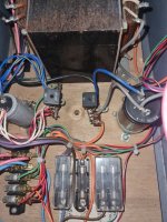
OK, I believe it's the solid red wires. I also marked the color of the wires from that bridge here to the cap because (see 2nd pic). I wish there was a clear copy of the schematic with color codes for the wiring. For such an amazing game, just to think only 1 page schematic and quite blurry. I still can't make some of the #'s out even with readers on.

This is what it looked like when I got it (Previous operator game). Never mind that it had a mouse nest in it but if you look closely, it wasn't as clear cut as it seems.
The rectifier was missing, it only had the bridge left, but they tapped it with the wrong color wires -and- I later found that the blue/yellow wires that were supposed to be coming off the positive lead of the rectifier were soldered to the negative side of the 4700uf cap and the white/red wires that were supposed to be coming off the negative lead of the rectifier were soldered to the positive side of the cap! Hence why it was originally blowing the 8amp fuses by the dozen when turned on. They were all over the bottom and they even tried a few 10amp one's.
I'm not sure if they tapped the bridge to try and run the motor manually somehow? but the presence of that additional wire needed coming off of the AC side was completely missing to the connection on the terminal which was why it was so difficult.

From what I can tell, even with that wire not hooked up, there might be a possibility of 11v AC in the line somewhere still getting to the brake light board and motor board which is why it still worked? However, an original motor board pcb performed the same way.
So, the entire red wire there was missing, so the rectifier wasn't getting AC and neither was the brake lamp, or the motor drive?
I'm amazed and baffled so much worked.
I'm amazed and baffled so much worked.
LoneWolf24
Newbie
- Credits
- 4CR
One AC wire was connected to the bridge for each side, however, the additional ac wire coming from the bridge to the terminal which then splits off into another two wires, one to the motor board and lamp board was missing.So, the entire red wire there was missing, so the rectifier wasn't getting AC and neither was the brake lamp, or the motor drive?
I'm amazed and baffled so much worked.
Ah, ok, makes a bit more sense now as the brake wouldn't have released at all without the rectifier properly connected.
So somehow the motor drive PCB was working without 18VAC. What makes that odd is it needs to have a proper connection to power the optocouplers and chunky resistors on the sense circuit. It should theoretically have sat there doing nothing or juddering around, out-of-sync - that's certainly how my test rig behaves.
Oh well, best not to overthink it. Maybe somehow the lamp board put a weak 11V onto it instead. I'll figure it out some day perhaps
LoneWolf24
Newbie
- Credits
- 4CR
One thing I noticed from the start, it's neither here nor there but I could never tell if an original motor board was working from day 1, meaning, there's no LED on the board anywhere, meaning the original design, yet the main pcb has a bright lit red led on it. One can measure I suppose but usually boards have a test points & lugs for voltages & some ground to work with, etc.Ah, ok, makes a bit more sense now as the brake wouldn't have released at all without the rectifier properly connected.
So somehow the motor drive PCB was working without 18VAC. What makes that odd is it needs to have a proper connection to power the optocouplers and chunky resistors on the sense circuit. It should theoretically have sat there doing nothing or juddering around, out-of-sync - that's certainly how my test rig behaves.
Oh well, best not to overthink it. Maybe somehow the lamp board put a weak 11V onto it instead. I'll figure it out some day perhaps
I always prefer original and a 1:1 reproduction but I wonder if in this case a few simple lights and test points indicating proper voltage would've benefitted the original design? For example, a red light power to indicate on, yellow light 18v if very close in voltage or not, or at least some clear test points.
No matter, I'm really glad we figured it out and can finally work on more of the details now/ play it!