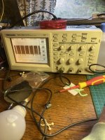
It's going to vary with the data!
You seem to be jumping around with your tests. Slice one moment then scope the next. You need to have a more methodical approach or you will just keep going back over the same stuff.
One thing is to make a Project in Slice, then you can capture results you get. Handy to look back over when tracing schematics and looking for signals.
The thing to note is that your basic gfx seem to be fine, it's just that their colours are completely screwed.
For instance the test screen, all the colour blocks are Blue, means no red or green is being enabled and blue is being enabled when it shouldn't. Also the background should be black but ends up being white which is all colours at max.
I think a possible fault is that the Palette ram at $9c00-$9cff is not being written correctly. A good place to start checking this is to look for the select signal that comes from the 74LS139 @2S pin 10 on the bottom board.
This goes into 74LS138 @ 8D pin 5 on the top board and generates the read / write signals for the palette ram.
The 74LS08 also has 2 gates used with these select signals, pins 8-13, these control the data buffers enable and direction control.