
You are using an out of date browser. It may not display this or other websites correctly.
You should upgrade or use an alternative browser.
You should upgrade or use an alternative browser.
LED Lights - Recommend me a controller
- Thread starter guddler
- Start date

chadsarcade
Lord of Vectors (tm)
guddler said:I get that with common anode, where +ve is the common no connection would be on, not off, but why then is analogWrite(rOUT, 255); (and 0 for blue and green), full red?
For that I'd expect to see Blue and Green full on and no red (my previous response related to your removing all inputs). Is this wired directly to the LED strip via your own drive transistors or are you hacking into the module and using its output stage? It's acting like the output is inverted.
chadsarcade
Lord of Vectors (tm)
trm said:A few people have already worked on decoding the remote. This is one dude's efforts:
http://www.instructables.com/id/Reverse-Engineering-RGB-LED-Bulb-with-IR-remote/
Nice link! There's an arduino library too which will includes a sniffer of the raw codes to the serial console as you press them.


So, here's the pictures of the controller...
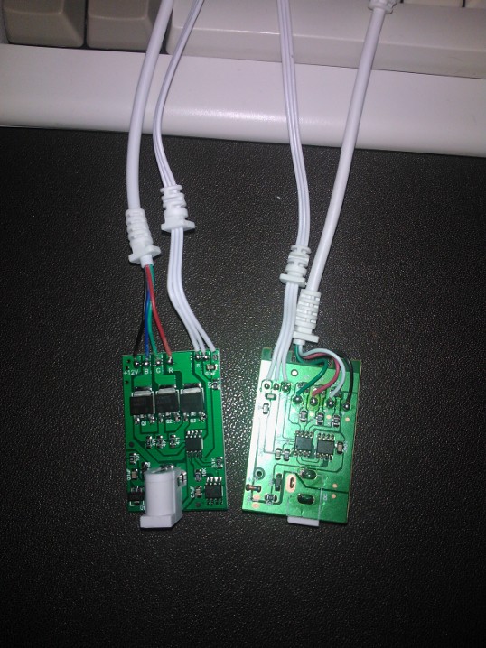
The new one bought last week is on the left, the one bought back in the summer is on the right. Have to admit, the one on the left actually looks up to the job and I think I'd trust it. Shame it's got a dud transistor!
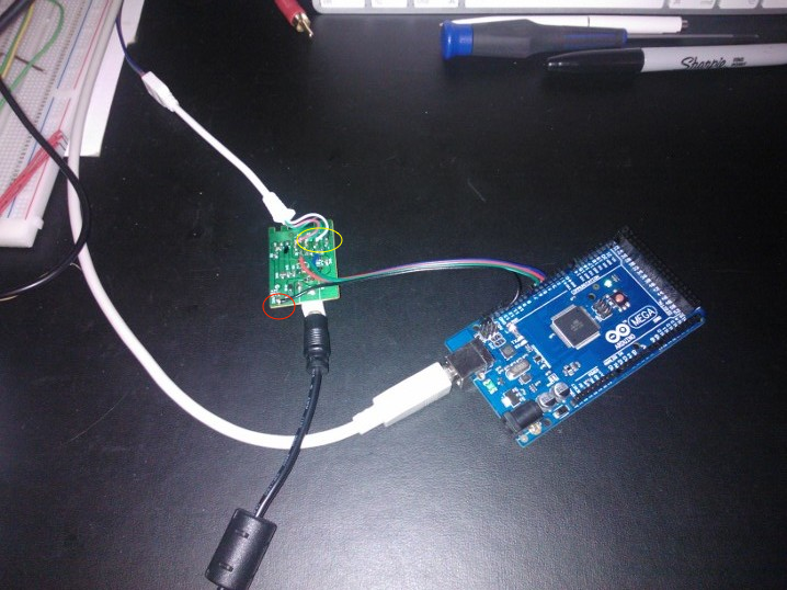
So, this is the other one hooked up to the Arduino (nowhere to buy SMT transistors round here before Xmas!). The red circled black wire is the GND connection between the 12v GND and the Arduino's GND. The yellow circled black wire is the +12v common anode. Don't really know why they chose to use black but hey, they did!
All I've done is remove the two ICs and connected the R/G/B wires from the Arduino PWM outputs to the side of the 1K resistors that used to be connected to the IC.
guddler2013-12-21 18:57:31
The new one bought last week is on the left, the one bought back in the summer is on the right. Have to admit, the one on the left actually looks up to the job and I think I'd trust it. Shame it's got a dud transistor!
So, this is the other one hooked up to the Arduino (nowhere to buy SMT transistors round here before Xmas!). The red circled black wire is the GND connection between the 12v GND and the Arduino's GND. The yellow circled black wire is the +12v common anode. Don't really know why they chose to use black but hey, they did!
All I've done is remove the two ICs and connected the R/G/B wires from the Arduino PWM outputs to the side of the 1K resistors that used to be connected to the IC.
guddler2013-12-21 18:57:31

guddler said:Oh, during the "working" period where I was actually quite positive about it, I had a think about what I wanted out of it and really, all I want is what the stock remote gives me.
(SNIP)
just needs a few shortcomings sorting out (only being able to fade down so far for one, bias adjustment for another).
I've been thinking about that and it seems a sensible approach, so I decoded the IR from a remote and have started modifying my code to first replicate the default functionality.
https://github.com/trmatthe/lightstrip
Can I shamelessly plug my own RGB controllers? I've been selling them as simple kits for a very long time. No remote control facilities since they are designed for stand-alone applications. Their main feature is a huge randomiser and software implemented colour palettes.
Designed for common anode arrays/strip with a current capability of 5A per channel.
These same controllers are used everywhere from the Las Vegas strip to various BBC series (in props and on set) and even in Disney's illuminated parades.
www.bigclive.com/shop.htm
[EDIT by Gudd] Just edited Link. Not really sure why but the forum was doing something odd!
guddler2013-12-23 00:12:38
Designed for common anode arrays/strip with a current capability of 5A per channel.
These same controllers are used everywhere from the Las Vegas strip to various BBC series (in props and on set) and even in Disney's illuminated parades.
www.bigclive.com/shop.htm
[EDIT by Gudd] Just edited Link. Not really sure why but the forum was doing something odd!
guddler2013-12-23 00:12:38
But the old single colour 5050 tape is so last year. The new kid on the block is the ws2812 which is an RGB LED and a serial chip in a standard 5050 package. Each chip takes three bytes from a data stream and then passes the data through so you effectively have individual colour control of every single LED in the string with just three wires. 0v, 5v and data. The software is a bitch though since you have to really hammer the data out. Any slight gap in the data and all the chips think the frame is complete, display it and then reset to the first LED again.
I started drooling over the serial addressable units shortly after ordering a bunch of the 5050 gear. Have you got a good supplier or am I stuck with Aliexpress for anything more than 10 units on a strip?
I figure clocking an AVR fast is the way forward because I like the coding environment, or maybe an AVR + shift register hack.
I figure clocking an AVR fast is the way forward because I like the coding environment, or maybe an AVR + shift register hack.
You might consider beefing your existing Chinese controllers up with an STP36NF06L MOSFET in place of the existing output transistors. Or better still, the SMD equivalent so it solders right in. The lower the on-state resistance of the MOSFET the more current you can control without a heatsink.
So my test pixel strip turned up. And they are AMAZING! I decided to go for a prewired strip in the end; when I got a ruler out and looked at the pitch of the WS2812B ICs I figured SMT was getting a bit too small for me to happily solder. Which turned out to be very true because I needed to attach the Vss, Vcc and MOSI line and f**ked the first LED with my Red Bull-shakes induced soldering  I knocked up a bit of code to learn the FastLED API and will ultimately be snipping these down to make a proto pixel panel, at some point to be replaced with a much larger one that I'll make XY addressable. I really want to code up an old-style Amiga demo plasma for one of these and hang it on the wall. Couple of vids to show my tests. First is a Williams style rainbow blur bar - http://www.youtube.com/watch?v=8AWKC9hHPh0 And the second is a rainbow Cylon - http://www.youtube.com/watch?v=4Oltc3NW4t8I've pretty much chucked my own code out of the window and am working with FastLED (aka FastSPI2). It's got hand crafted assembly to keep things flying along, has reimplemented my clamping colour routines and includes RGB & HSV colourspace functionality. Definitely worth a look IMO https://github.com/FastLED/FastLED/wiki I'm not sure how clear it is from the video but these seem to be 5050 RGB equivalent and even better resistor balanced than my good 5050 strip. I'm using a 30ms delay between updates in the videos. With 60 LEDs on the 1m strip and no delay I can update the strip faster than the LEDs can keep up using a 16MHz AVRMega 1280. So I reckon I'm probably good for about 300-ish WS2812Bs at wire-speed. My desired panel would ideally be about 6-700 pixels so I think I'll have to move to a Teensy 3.1 for that, but we'll see. The strip was £19.99 from eBay and sucks about 1.5A@5V when I've got the full strip cycling rainbows. Need to start looking at building a 20A PSU... Yeah, cat in the first vid. This is the last update I'll post to this OT thread. Follow-ups to http://www.ukvac.com/forum/ot-arduino-and-web-control-for-rgb-lightstrip_topic336496.html |
Sadly all my LED shenanigans stopped when the PSU sh*t itself and died. We're decorating the living room towards March so at that point I'm going to revisit it all but I'm seriously considering just going for white as I only really need fade, not pretty colours!
chadsarcade
Lord of Vectors (tm)
Whilst Tim is off in the land of pixel strips, I've found some time to play with the arduino and replicate the functionality of the original el-cheapo RBG controller.
I've gone for an HSL colourspace which makes the colour transitions nice and easy, and the remote functions are more or less replicated.
Last night I coded the R/G/B up and down buttons to change the overall bias of the R/G/B channels on the fly. Setting the output to "white" (which is far from white on the original controller) I managed to adjust the levels to get a pretty acceptable white colour with:
R = 100%
G = 30%
B = 45%
These settings have also vastly improved the colours across the board - Hue 60 is now a pretty good yellow, rather than a pale green with the default all channels = 100%
This shows the default balance is way off, though I wonder if it might be possible to mod the original controller to reduce the values to match?
What I need to do now is adjust the saturation and brightness controls to match more closely human perception, as most visible changes happen within about 20% of their range as it stands.
I've gone for an HSL colourspace which makes the colour transitions nice and easy, and the remote functions are more or less replicated.
Last night I coded the R/G/B up and down buttons to change the overall bias of the R/G/B channels on the fly. Setting the output to "white" (which is far from white on the original controller) I managed to adjust the levels to get a pretty acceptable white colour with:
R = 100%
G = 30%
B = 45%
These settings have also vastly improved the colours across the board - Hue 60 is now a pretty good yellow, rather than a pale green with the default all channels = 100%
This shows the default balance is way off, though I wonder if it might be possible to mod the original controller to reduce the values to match?
What I need to do now is adjust the saturation and brightness controls to match more closely human perception, as most visible changes happen within about 20% of their range as it stands.
When I designed my simple knob based controller (fnar, fnar) I built the facility for calibration into the software so you can put it into calibration mode and step between R,G and B to tweak their intensities to get a neutral white. That also allows a crude colour temperature control in the circle of colours the knob spins through by modulating the blue while the red and green are at full output.
chadsarcade
Lord of Vectors (tm)
Cheers for that info Clive, I hadn't thought about how colour temp worked before.
Having now wired up the "warm white" strip to the same controller and have them side by side, I can see how different the "white" generated by the RGB strip is in comparison. I may have a play with tweaking the blue level further - I guess reducing it should make the white a bit more yellow which may do the job.
Having now wired up the "warm white" strip to the same controller and have them side by side, I can see how different the "white" generated by the RGB strip is in comparison. I may have a play with tweaking the blue level further - I guess reducing it should make the white a bit more yellow which may do the job.
Chad - you got any code I can try please? I'm going to want a decision before too long whether to bother with RGB at all when I decorate or just to say to hell with it all and go for white LEDs instead.
Regardless, I'm going to need to find somewhere reliable to buy from. Cheap eBay Chinese crap has been a nightmare for me.
Regardless, I'm going to need to find somewhere reliable to buy from. Cheap eBay Chinese crap has been a nightmare for me.