
You are using an out of date browser. It may not display this or other websites correctly.
You should upgrade or use an alternative browser.
You should upgrade or use an alternative browser.
System 1 Atari ,how to power amp from switcher ?
- Thread starter Body pop
- Start date


Yeah I’m a member .
I’ll go over there and see what I can find as I’ve moved on quite a bit since last searching for something different
I’d wondered about that -11 and if -5 would do too when I saw it
Thanks again for all the superb help 👍
I’ll go over there and see what I can find as I’ve moved on quite a bit since last searching for something different
I’d wondered about that -11 and if -5 would do too when I saw it
Thanks again for all the superb help 👍
Klov has changed from last time I was on
Need a recommendation now etc to post
I might try the 12 v after market amp thing that @muddymusic done in that thread I quote
Would it just be the case of leaving it wired as far as we got.
As it needed that audio 2 board to boot
Then feeding another 12 v into the aftermarket amp and connecting the speakers
As it needed that audio 2 board to boot
I’ve now wired in a small amp
I’ve made a connector ,with the two grounds and left and right audio
From connector p 105
The reset isn’t connected to anywhere though
So apart from wiring the speakers to this amp
12 and ground to amp from switcher
I’ve no sound ,but probably because I’ve still the audio 2 board connected so the game boots
Pics of what’s still coneected
Attachments


On your external amp you should have input side from the game board [ unamplified sound ] then an output side [ amplied sound ] to speakers
P105 — Sound Connector (to Audio/Regulator Board)
P105 — Sound Connector (to Audio/Regulator Board)
- 1: Self Test
- 2: Right RTN (Audio Ground)
- 3: Right Audio
- 4: Left RTN (Audio Ground)
- 5: Key
- 6: Left Audio [1]
Thanks for the reply
I used this
Hacked the aux connector
Looks like I’ve messed ut up quite badly
I had read
Connect pins 2 and 4 the grounds to the ground of the spliced wire
Then connect the other two
Left and right to left and right of this spliced wire
Then connected speakers from the cab and 12v
I used this
Hacked the aux connector
Looks like I’ve messed ut up quite badly
I had read
Connect pins 2 and 4 the grounds to the ground of the spliced wire
Then connect the other two
Left and right to left and right of this spliced wire
Then connected speakers from the cab and 12v
Attachments

When i built an Atari system 1 jamma adapter and knew the original Atari Audio board used a TDA2030 amp chip so I bought an external amp like this so the sound would be authentic as possible.
Have to check that amp and see what connections you needThanks for the reply
I used this
Hacked the aux connector
Looks like I’ve messed ut up quite badly
I had read
Connect pins 2 and 4 the grounds to the ground of the spliced wire
Then connect the other two
Left and right to left and right of this spliced wire
Then connected speakers from the cab and 12v
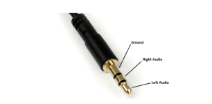
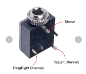
Pins 2 and 4 from board will go to the combined Jack plug Ground then Pin3 (P105) to where the tip connects to on the audio female jack connector on the audio board then 6 (P105) to where the Right Audio (middle section) of the jack connects to on the audio board. If you can find the pinout of a female PCB mounted jack connector then you will know where to connect on the amp board with the female jack connector removed.

great stuff . many thanks for thisView attachment 66758
Pins 2 and 4 from board will go to the combined Jack plug Ground then Pin3 (P105) to where the tip connects to on the audio female jack connector on the audio board then 6 (P105) to where the Right Audio (middle section) of the jack connects to on the audio board. If you can find the pinout of a female PCB mounted jack connector then you will know where to connect on the amp board with the female jack connector removed.
No problem, let us know how you get on wiring the audio up and if you get soundgreat stuff . many thanks for this
No problem, let us know how you get on wiring the audio up and if you get sound
I had just hacked into the actual aux connector wire and was still using the male aux part
One other thing please
How did you get the game to boot without the audio 2 board
Did you connnetf pin 1 the reset the switcher
As when I remove the audio 2 complety I get the garbled screen
Of it not booting
I never had an Audio 2 board to start with I just bought the Sys 1 mainboard plus the seperate cartridge boards and wired the mainboard up for Jamma. I never had an issue with the board not booting minus an AR2 board, just with an external amp connected it worked fine. I did have to do some trick wiring for Indiana Jones by sending the +5v required for joystick movement through several small relays. My joystick grounded each relay to provide the relative isolated +5v movement response back to the board. I can't get to my setup as it's in storage at the moment to check the connections but going over this Sunday so maybe able to check afyer that if you are still having issues.
Did you read this thread at all?
Help with bench testing Atari System 1 setup
I'm trying to put the System 1 cab back together, it's a bit of a mess of wiring. The AR3 is long gone and the transformer has been messed about with. I'll be running it off a switcher. I want to get the pcb running on the bench first. I've got an Audio 2 pcb (not an AR2) for the sound...
www.ukvac.com
I take it you hooked up pin 4 of the P101 to 12v to stop the board from resetting?
1 - RTN
2 - + Sense
3 - +5vdc
4 - +10.3vdc reset (connected to 10.3v unreg from Audio Reg III PCB)
5 - -sense
6 - -15vdc
7 - N/C
8 - RTN
9 - +15vdc
10 - +5vdc
11 - +5vdc
12 - RTN
1 - RTN
2 - + Sense
3 - +5vdc
4 - +10.3vdc reset (connected to 10.3v unreg from Audio Reg III PCB)
5 - -sense
6 - -15vdc
7 - N/C
8 - RTN
9 - +15vdc
10 - +5vdc
11 - +5vdc
12 - RTN