
You are using an out of date browser. It may not display this or other websites correctly.
You should upgrade or use an alternative browser.
You should upgrade or use an alternative browser.
Bombjack ram location
- Thread starter Retroman839
- Start date


Thanks sukhbir
Awsome …You have the Schematics I presume?
There isn't much between ram and cpu, and only a few chips handle the select for rom/ram/IO.
Unusually it uses a bunch of 74LS86's to handle address line buffering. These are @ 2J-2M, basically next row to program eproms.
74LS139 @ 3M, 74LS138 @ 4M & 5M handle main bulk of addressing.
74LS32 @ 7T & 3H, 74LS27 @ 1C handle some of the control lines.
74LS245 @ 2H sits on the data bus and 74LS20 @ 6N controls enable.
You should also be able to use the schematics and buzz the address/data lines with a meter to check for connection.
And of course Slice will identify any inputs that are floating using the Float test.
Thanks for that
That will help loads !
Hunting time !
Last edited:

Monstermug
Active member
I love the way you approach repairs so technical and systematically. Spoken like a true guru that you are.You have the Schematics I presume?
There isn't much between ram and cpu, and only a few chips handle the select for rom/ram/IO.
Unusually it uses a bunch of 74LS86's to handle address line buffering. These are @ 2J-2M, basically next row to program eproms.
74LS139 @ 3M, 74LS138 @ 4M & 5M handle main bulk of addressing.
74LS32 @ 7T & 3H, 74LS27 @ 1C handle some of the control lines.
74LS245 @ 2H sits on the data bus and 74LS20 @ 6N controls enable.
You should also be able to use the schematics and buzz the address/data lines with a meter to check for connection.
And of course Slice will identify any inputs that are floating using the Float test.
@ OP: A road map of how to fix right there. Don't forget to update slice to latest version and set propagation and lastly in his famous words... RTFM whatever that means.
 If that fails then check under GFX roms for scratched traces and sockets for continuity.
I most definatly will do this 😊I love the way you approach repairs so technical and systematically. Spoken like a true guru that you are.
@ OP: A road map of how to fix right there. Don't forget to update slice to latest version and set propagation and lastly in his famous words... RTFM whatever that means.
Thanks gadget freak 👍
answer to your question about schematic,
Yes somewhere on web page on my phone .. not ideal !
But yeh I looked at the 2 rams between the cpu & EPROMs
Thanks for expalining to me thr upper and lower part also as I could see this on the schimatic but I didn’t understand it.
So much ttl all over this just to drive the vídeo ..
I’m hoping the colour issue is around these 2 2116’s Pallet rams. I think I have established it’s not the ram itself at fault by replacing it with like for like and issue persists ,
Hence now thinking broken trace or buffers perhaps

i rememberd you mentioned the logic shop !
I do have one of their PCB’s 👍
Last edited:

All my first pcb's were dug out of their skip back in the mid 80'si rememberd you mentioned the logic shop !
I do have one of their PCB’s 👍
Going back to BJ.
The video & colour ram is the 2128 @ 6LM on the top board, this is the 0.6" one on the 3rd row of chips back from the ribbon cable.
The palette ram is 3 x 2114, 6A is Red, 6B is Green & 6C is Blue. These are on the same row as video ram but on the other side of the board.
Thanks for thatAll my first pcb's were dug out of their skip back in the mid 80's
Going back to BJ.
The video & colour ram is the 2128 @ 6LM on the top board, this is the 0.6" one on the 3rd row of chips back from the ribbon cable.
The palette ram is 3 x 2114, 6A is Red, 6B is Green & 6C is Blue. These are on the same row as video ram but on the other side of the board.

Cheers for that will take a look & the 2128 Could be these
74ls174’s handle rgb also right next to the rgbs header ..
Iv orderd new for these also .
good score to pull pcbs from ops waste store back in the day 👍

Schimatic has these 2x. 194’s @ 6L
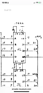

As soon as man flu lets me crawl out of my bed i will be ..
Already orderd replacement.
I have all Clours but in wrong order ..

Already orderd replacement.
I have all Clours but in wrong order ..
Rgb then feed into the 174 x2
Slice is on with floating pins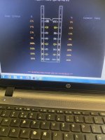
My Clíp not making contact ?
Will scope the clk
Slice is on with floating pins
My Clíp not making contact ?
Will scope the clk
Last edited:

Good clk on both 174’s
Will try slicing the other 174
ASAP ,
Little segway

dot/dimple is on opposite side on my 74ls74!
Non compatible ?
Thanks i Can ignore the small circle then 👍The end with the cutout/dimple is the end with pin1/pin14. They are compatible.
The two 174’s thst handle the rgb right next to the rgb out put
Have good clocks and i watched the game with logic probe on some address lines and thst had good oscilación corospondimg with game changes ..
But i guess they could still have 1 fault and the rgb could be screwy like it is ..
I’m going to try Piggy backing them with new.
Ok with slice attatched with a 20 pin clip on an 18 dip chip.
Pin 5 through to 12 floating and i get same result on the other 174,
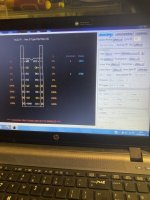
Second 174
Slice float check result

Same bottom half bad ?
Last edited:
Yeh i will do that ..👍From the colour of the legs they need a clean before you try slicing them. Fiberglass pen is the best for that I have found.
Last time i used fiber glass pen loads of bristles on the loose !

Hairs all over the place ..
Will do thst outside from now on ,

Last edited:
Are you sure you have the clip on the cable correctly. A 20 pin clip should line up with the end of the cable pcbs, ie furthest away from the 2x3 pin connectors.Pin 5 through to 12 floating and i get same result on the other 174,
Second 174
Slice float check result
Same bottom half bad ?
Also make sure you have the on screen chip in the right pin locations if not using Auto Shift.
Your right , I do have it connected incorrectly in that case , thanksAre you sure you have the clip on the cable correctly. A 20 pin clip should line up with the end of the cable pcbs, ie furthest away from the 2x3 pin connectors.
Also make sure you have the on screen chip in the right pin locations if not using Auto Shift.
I had suspected as much,
Reading manual now,☺️
Pin 1 on the pin 1 side of the ic always ! ( flexibility to move clip left & right )
This is what through me .👍.
Last edited:
Apolagies for the delay
Covid.2
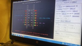
Here is my slice result
On the 74ls74 @ 7a top board

And 74ls74 Fuji @ 8b top board

No floating pins on either .
After changing set up time to 10ns I get

Zero error states ..
Safe to say these to 74ls174 are good
Covid.2
Here is my slice result
On the 74ls74 @ 7a top board
And 74ls74 Fuji @ 8b top board
No floating pins on either .
After changing set up time to 10ns I get
Zero error states ..
Safe to say these to 74ls174 are good
Attachments

Last edited:
