Yet another SubElectro MC type Fantazia/Pisces ???

NivagSwerdna

Active member
Feedback
1 (100%)
Credits
744CR
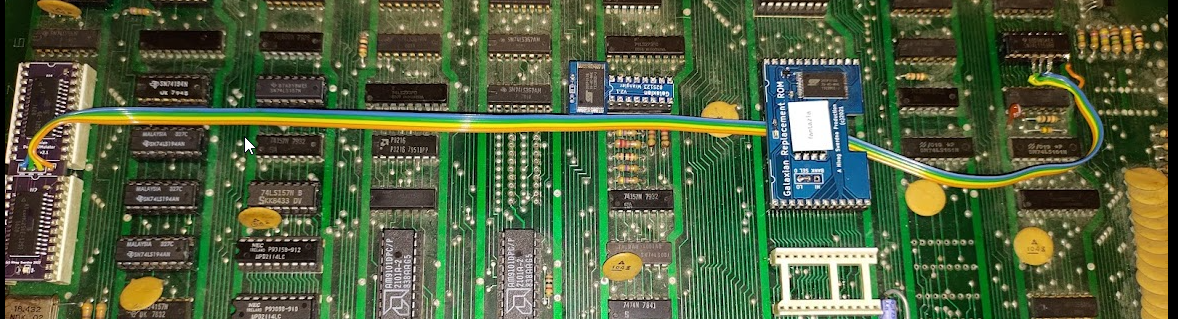
Was slightly clutching at straws since essentially the sprite rendering hardware is mostly working but decided to change 3L as that gets a pretty hard life... removed, socketed and replaced with new... no change. OK well that was a guess.

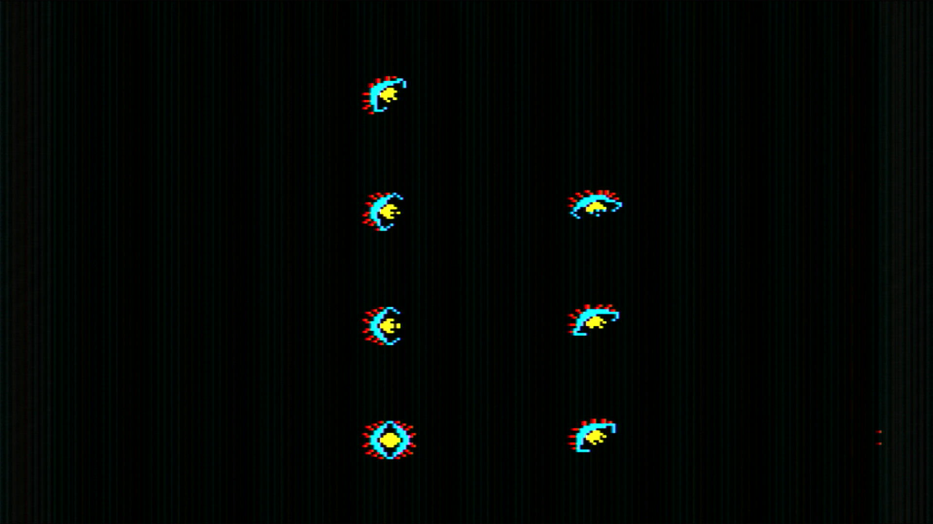
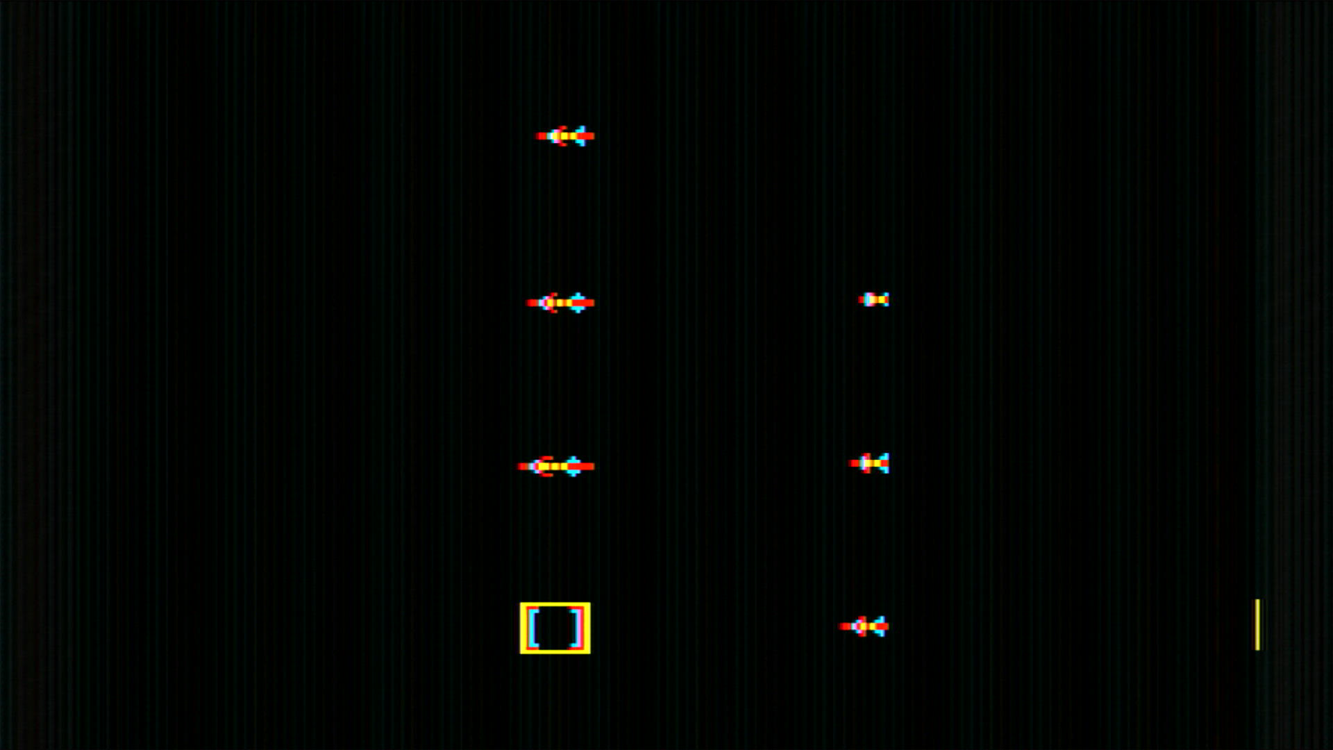
Fiddled around with pressing the board and seemed to get some variation but couldn't find a pattern and then I thought I should possibly fiddle with the voltages so twiddled the knob on the PSU and turned the voltage slightly down...

Screenshot_2022-08-22_13-58-10.png


Fully rendered sprites with no sparkles... go figure.

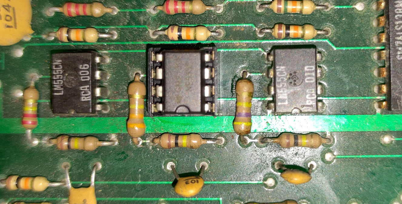
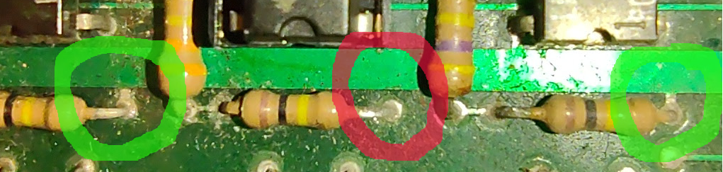
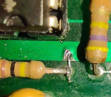
I think I might make an effort to replace the missing/broken bypass caps sprinkled around the board...

I still have to figure out a board for the bank switching and also test the SFX... I'm also slightly suspicious of some artifacts I have seen when updating the colour/scroll position for characters...
 

Vamino

Insert coin(s)
vacBacker
Feedback
22 (100%)
Credits
2,621CR
Great progress!

Seems like you are very close now.

I've got a similar issue with voltages on a Mr Do! that glitches at 5v but works fine at 4.74v. No idea what causes that.
 

NivagSwerdna

Active member
Feedback
1 (100%)
Credits
744CR
I don't know if this is an excommunicable offense but I'm going to remove the onboard audio amp and route the audio out to pin 22 on the edge connector... and then onwards to JAMMA p10 and off to an audio amp.

CaptureAudioAmp.png


Do people tend to keep the onboard amps? I have removed the regulation part of the board previously so it is simply 5V in with no need for 12V.
 

NivagSwerdna

Active member
Feedback
1 (100%)
Credits
744CR
Did that... so have unamplified sound going out to the connector... added external amp and speaker and I have some noise...

CaptureFixedOscillators.png


I seem to have FS2 missing... Cannot spot any oscillation at p3 of 8S... I must have a 555 somewhere but haven't seen in for probably >5yrs!

The measured frequencies of 8R and 8T don't match my expectations which is a bit odd... I see 218Hz and 468Hz... I guess the capacitors might be off... but it's quite a big difference.

Tunes seem to play OK... so 9K/8K/6E etc must all be good.

Probably just need to replace 8S.
 

NivagSwerdna

Active member
Feedback
1 (100%)
Credits
744CR
Whilst waiting for the Post Office to stop striking I got to thinking about how to do the Graphics ROMs... Macro alluded to using bigger ROMs and I'm thinking it might be good to use a pair of 16K ROMs and to just use the address space to eliminate the need for any extra decoding circuit (as found on the current daughter board). I actually have a small stash of 32K ROMs from a previous project that probably will never get used so that's a cheap option for me.

SpritesFantazia.png


SpritesPisces.png


SpritesMooncrst.png


SpritesMooncrs2.png


I think these are the sprite maps from the ROMs in fantazia, pisces, mooncrst and mooncrs2.

I have a mooncrs2 which has some interesting extra circuitry (stacked chips) and uses 2732s

Now I have to figure out how to map these sprites into 16K in such a way that GFX2, GFX1 and GFX0 from the latch can be used as address lines without breaking any of the mapping.

PS

I'm thinking of making this board into pisces now (which matches the current colour PROM) rather than fantazia (which I had previously expected)
 

NivagSwerdna

Active member
Feedback
1 (100%)
Credits
744CR
Incidentally MAME has a strange definition for the mooncrs2 GFX ROMs...

CaptureMAMEmooncrs2gfx.png


This is a bit bizarre... MAME swaps the middle sections of the sprite map... will have to think about that!

You can actually see this in the sprite maps above... mooncrst and mooncrs2 differ on rows 6 and 7... they appear swapped... I guess you would need to play a game through on real hardware to see if that swap is legitimate.

NivagSwerdna2022-09-02 17:54:16
 

NivagSwerdna

Active member
Feedback
1 (100%)
Credits
744CR
My 555s arrived so I duly removed 8S, socketed and replaced with a new 555... and it still doesn't work... started to doubt myself so retraced to the 9R and mini-DAC etc that generates a cutoff waveform, even doubted the latch 9M and the decoding 8M but the other two 8R and 8T are working OK so it cannot really be those.

CaptureWotNoFS2.png


And then I spotted it... one of these things is not like the other... one of these things does not belong! Must have been a manufacturing defect and has never worked...

But can you spot it?
 

jbtech

Newbie
Credits
56CR
Hi, I would guess it's the 15k resistor as it looks like the only value which doesn't follow a pattern - but can't see in the photo where else it connects to... Regards, John.
 

NivagSwerdna

Active member
Feedback
1 (100%)
Credits
744CR
Macro said:
middle lower resistor not connected to anything ?
We have a winner. If you look carefully the right hand side of each of the three lower resistors (which are for pin 7 of the 555s) should be connected to the 5V fat track, but either in layout or manufacturing it is missing from the middle one.
CaptureMissingTrace.png


and bodged...

CaptureBodgeWire.png


I don't think the resistor appreciated being sprayed with Isopropyl Alcohol as I cleaned the area! Sorry!

NivagSwerdna2022-09-05 12:32:13
 

NivagSwerdna

Active member
Feedback
1 (100%)
Credits
744CR
A few life events are getting in the way of my completing this but I soldier on when I have a few mins...

CaptureR34b.png


Although the parts are not labelled on this bootleg board you can see R34 on the bottom right. It has what I think is 15k value whereas the schematic has 5.1k... I have seen this before... I will drop the value. I also think my mod for an external amplifier was wrong... I need to keep the value across R91 as 10k so I think I messed up the output impedance there.

It's interesting that the schematic considers R34 so important it appears twice!
smiley2.gif


CaptureR34.png


At least all the SFX are working OK... just a case of getting the relative levels fixed.
 

TheDaddy

Senior Member
vacBacker
Feedback
14 (93%)
Credits
6,994CR
Ye its defo a 15k, Or so my handy tool tells me (Ye lazy I know !) :-

15k.JPG


You do get some schematics there are incorrect - Its looks old so probably factory fitted maybe ?

Dave.
 

NivagSwerdna

Active member
Feedback
1 (100%)
Credits
744CR
TheDaddy said:
Haha oh crumbs , I get mixed up sometimes with colours. The tool would not even help you sadly.
To be fair I think I get them right... it just takes concentration. As a cyclist it helps with traffic lights... never encountered a red one yet.
smiley2.gif
 

TheDaddy

Senior Member
vacBacker
Feedback
14 (93%)
Credits
6,994CR
NivagSwerdna said:
TheDaddy said:
Haha oh crumbs , I get mixed up sometimes with colours. The tool would not even help you sadly.
To be fair I think I get them right... it just takes concentration. As a cyclist it helps with traffic lights... never encountered a red one yet.
smiley2.gif

Haha I dont think that will hold up in court when you run a red light ! But always worth a go.

Dave.
 

NivagSwerdna

Active member
Feedback
1 (100%)
Credits
744CR
Eventually got back my latest creation from the China PCB factory...

CaptureBank1.png


Possibly not the most cost efficient solution but I have a small stash of 32kx8 AT28HC256E-12SI so these are effectively free to me. The idea being that with a pair of 32k devices (actually only 16k required) we can do away with the 74LS10 on the original daughterboard. So... GFX2, GFX1, GFX0 become high bits to the GFX ROM address rather than muxing is as A9 and A10.

CaptureBank2.png


so in total...

CaptureBank3.png


and a bit of testing...


Bank4.png


Bank5.png


Bank6.png


Bank7.png


so I think we are working.


I notice a bit of misbehaviour with contention between writes to video ram so need to investigate that... and once that is done I think we are ready to try and fire up the game...
 

NivagSwerdna

Active member
Feedback
1 (100%)
Credits
744CR
Hm... put in a Z80...

Screenshot_2022-09-24_20-55-59.png


Game play is correct.... but the video is screwed up... I slightly suspected this might happen when I earlier saw artifacts whilst filling video memory... will have to think about it... looks like contention between the CPU and drawing since it appears correct when the image is static

https://youtu.be/3d0n_fRBSVQ

NivagSwerdna2022-09-24 21:23:59
 

Macro

Active member
vacBacker
Feedback
4 (100%)
Credits
1,982CR
Pin 24 of the Z80 (labelled /WREQ on the galaxian schematics) is actually the /WAIT line and is driven by a 7474 at 6S to only allow writes in the blanking period. check that is toggling correctly.
 
Top