I don't know how useful wiring from other cabinets will be since your cab is Italian and doesn't seem to follow what Atari did? The board is the same and official Atari one though? If so I'd start there and work backwards, the pinout for the board will be documented.
You are using an out of date browser. It may not display this or other websites correctly.
You should upgrade or use an alternative browser.
You should upgrade or use an alternative browser.
Solved Atari power supply help
- Thread starter Body pop
- Start date
So this is info on Paperboy, not sure if needs all the voltages same on 720 as it doesn't have analogue pots like the other Sys2 games
To test and adjust the voltages for an Atari Paperboy arcade board, measure directly on the logic or CPU board to account for voltage drops.
+5V DC: Target 5.0v to 5.2v
+15V DC: Used for the sound/audio amplifier.
-15V DC: Used for the audio section and op-amps. (speech from what can make out)
-5V DC: Derived from the -15V rail and required for sound and control inputs
Unregulated 10.3V: Typically reads between 12v and 15v (this running high is normal)
Looks like Paperboy it was just a 5V PSU as per my photo and that was replaced with Jamma one so on PB it's a very easy job if you have a +5v fail
https://www.ukvac.com/forum/threads/atari-system-2-pcb-repair-paperboy.43903/page-2
taken from PCB Thread

As Purity was saying below
This is incredibly confusing!

I have wired up my AR3 and brick exactly to the CPU and Video board as illustrated in the Paperboy manual.
However I can see that in the CS manual it definitely has +15v as Power OK instead of 10.3V DC so I agree with that
Where is the -5 volt connected? It mentions nothing about this on the wiring diagrams, but I can obviously see -5 being referred to at the 7905 as already mentioned. I currently do not have a -5 volt connected.
This is probably why my speech doesn't work etc!
What I've wired up to power is:
Video PCB:
P13
Pins 1,4 Ground
Pins 5,8 +5
Pins 9 +sense
Pins 11 -sense
Pin7 +15v
CPU PCB:
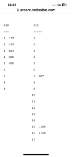
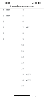
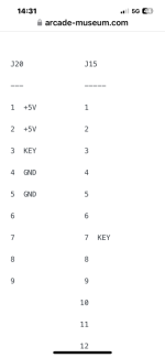
P15
Pins 1 Ground
Pins 2 +15v
Pins 3 -15v
Pins 4 10.3v
P20
Pins 1 -sense
Pins 2 +sense
Pins 3,5 Ground
Pins 6,8,9 +5
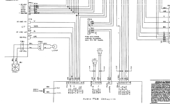
Looking at the 720 schematics page 4a (which are most convenient for me to locate) it looks to make -5v from the -15v input.
I have dug out my test loom, which I haven't used in years (and very nasty it is too) unless a wire has dropped off the loom I only have connections for gnd, +5 and +15v (sub labelled by me as +12v). I was originally testing for a non booting CPU so probably never needed/cared about -5v for speech. I might find the time to plug it in to a variable PSU and see if it actually works on +12v or only +15v rather than me idly speculating about what voltage I stuffed down it. It's been a looong time since I used it.
Thanks Karl. Yes I agree it looks like the -5 comes from the -15v, so that should be covered. I will check I am getting -5 at the 7905 but I suspect I will be doing, and I have sound issues elsewhere
I definitely think we need some answers on what power options work and what doesn't work
Well as promised I successfully fired up a pcb (champ sprint converted from paperboy) on +5vdc and +12v dc only. I also shut off the power rail that was connected to the +15v line and then managed to get the pcb to boot back up on it when powered back up at voltages between 6.5vdc and 14vdc so while I'm sure that will vary a bit between boards it's hardly fussy, the only difference was the quality of the video output (as someone previously suggested), though it looks a bit rubbish on my monitor/g-nobbers converter anyway.
It's an old loom but looking at it I clearly never bothered wiring up the 10.3 volt mentioned or the -15v. Just tied all the GND and +5v sense wires to the relevant rails (I don't think the sense wires are even connected on later System 2 cabs such as 720/APB that use 1x SMPSU) then stuffed +12v down P15 pin 2 on the cpu board and pin 7 of the video pcb.
I should reiterate that I have no amp, speakers or control inputs wired up to it to test I suppose you may well need that -15v if you are working on the sound section or some random controller dac. As regards the 10.3 volt... anyone decided what that is for without pouring over the schematics, if anything. From memory some Atari games of that era used an unregulated voltage from somewhere to guess when the power had been switched off so it could write to the novram before the power supply collapsed.
PS game board has a running current of about 9 amps on +5vdc according to my psu.
To test and adjust the voltages for an Atari Paperboy arcade board, measure directly on the logic or CPU board to account for voltage drops.
+5V DC: Target 5.0v to 5.2v
+15V DC: Used for the sound/audio amplifier.
-15V DC: Used for the audio section and op-amps. (speech from what can make out)
-5V DC: Derived from the -15V rail and required for sound and control inputs
Unregulated 10.3V: Typically reads between 12v and 15v (this running high is normal)
Looks like Paperboy it was just a 5V PSU as per my photo and that was replaced with Jamma one so on PB it's a very easy job if you have a +5v fail
https://www.ukvac.com/forum/threads/atari-system-2-pcb-repair-paperboy.43903/page-2
taken from PCB Thread
As Purity was saying below
This is incredibly confusing!
I have wired up my AR3 and brick exactly to the CPU and Video board as illustrated in the Paperboy manual.
However I can see that in the CS manual it definitely has +15v as Power OK instead of 10.3V DC so I agree with that
Where is the -5 volt connected? It mentions nothing about this on the wiring diagrams, but I can obviously see -5 being referred to at the 7905 as already mentioned. I currently do not have a -5 volt connected.
This is probably why my speech doesn't work etc!
What I've wired up to power is:
Video PCB:
P13
Pins 1,4 Ground
Pins 5,8 +5
Pins 9 +sense
Pins 11 -sense
Pin7 +15v
CPU PCB:
P15
Pins 1 Ground
Pins 2 +15v
Pins 3 -15v
Pins 4 10.3v
P20
Pins 1 -sense
Pins 2 +sense
Pins 3,5 Ground
Pins 6,8,9 +5
Looking at the 720 schematics page 4a (which are most convenient for me to locate) it looks to make -5v from the -15v input.
I have dug out my test loom, which I haven't used in years (and very nasty it is too) unless a wire has dropped off the loom I only have connections for gnd, +5 and +15v (sub labelled by me as +12v). I was originally testing for a non booting CPU so probably never needed/cared about -5v for speech. I might find the time to plug it in to a variable PSU and see if it actually works on +12v or only +15v rather than me idly speculating about what voltage I stuffed down it. It's been a looong time since I used it.
Thanks Karl. Yes I agree it looks like the -5 comes from the -15v, so that should be covered. I will check I am getting -5 at the 7905 but I suspect I will be doing, and I have sound issues elsewhere
I definitely think we need some answers on what power options work and what doesn't work
Well as promised I successfully fired up a pcb (champ sprint converted from paperboy) on +5vdc and +12v dc only. I also shut off the power rail that was connected to the +15v line and then managed to get the pcb to boot back up on it when powered back up at voltages between 6.5vdc and 14vdc so while I'm sure that will vary a bit between boards it's hardly fussy, the only difference was the quality of the video output (as someone previously suggested), though it looks a bit rubbish on my monitor/g-nobbers converter anyway.
It's an old loom but looking at it I clearly never bothered wiring up the 10.3 volt mentioned or the -15v. Just tied all the GND and +5v sense wires to the relevant rails (I don't think the sense wires are even connected on later System 2 cabs such as 720/APB that use 1x SMPSU) then stuffed +12v down P15 pin 2 on the cpu board and pin 7 of the video pcb.
I should reiterate that I have no amp, speakers or control inputs wired up to it to test I suppose you may well need that -15v if you are working on the sound section or some random controller dac. As regards the 10.3 volt... anyone decided what that is for without pouring over the schematics, if anything. From memory some Atari games of that era used an unregulated voltage from somewhere to guess when the power had been switched off so it could write to the novram before the power supply collapsed.
PS game board has a running current of about 9 amps on +5vdc according to my psu.
Last edited:


Great info bods .thanks 😀
Have you measured all the voltages at the PCB, to see what you are missing, is it just 5v you aren't getting mainly?
Just wondering how many Voltages that PSU is giving out, from what i've seen so far it's the +5v and +15v and -15v
Was never quite sure about the sense + and -
Has the 720 got this Audio II amp (was getting mixed up with ARII)

It doesn’t have the audio amp
I’m going to go through everything today again
I checked the 15 v and it was there at the board connector
I don’t see any test points on boards for it
The 5v is going to the connectors but the one going to cpu drops away down .other 5v going to video board appears to be ok ,though it was very high
I’ll have another look at the three voltage pots ,but that wouldn’t really explain why it’s dropping off
Unless the sense is doing something as the voltage is too high
So lots happening with this today
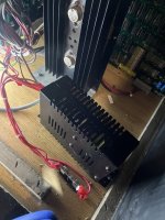
5vs and grounds connected to cheap switcher
To my surprise it came on
Sound missing though
I noticed there was a wire had came off the volume control
Soldered it on
Sound back,but game resetting
Checked voltage at board
Only getting 4.6
Moved it up to slightly over 5v
Everything working !
Played a game ,
Tidied everything up and played another quick game
Game started resetting then died
Switcher dead
I’d also removed the broken fan
Hoping the cheap power supply just wasn’t up to the giant pcbs
Has anyone any links for a decent switcher in uk ?
Attachments
Ah so close.
https://uk.rs-online.com/web/p/switching-power-supplies/6447023
26AMP! that should do it.")
https://uk.rs-online.com/web/p/switching-power-supplies/6447023
26AMP! that should do it.
Thanks for all the help with this
Some great help from amazingly helpful members
Take a bow 😀
I had an old hang on switcher that only has 5v on it
Often wondered what I would use it for .
It’s now in this and touch wood and everything ,it’s behaving 🤞
I’ll get one of those ordered above
For when or if this one dies
If it doesn’t I won’t be going near it again lol
Flipping aching lying under it ,banging my head on the bit that over hangs
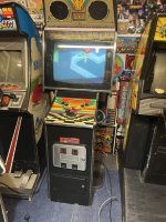
But and a very big but ,a seriously rare ,maybe the only in existence 720 and my fav game is looking
Good again
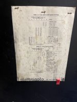
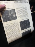
When I was in the back the sheet on the back door ,fell down revealing technical stuff on the other side
I’m just glad it wasn’t schematics for that power supply hiding there 🤣
Thanks again guys ,until the next time .
Some great help from amazingly helpful members
Take a bow 😀
I had an old hang on switcher that only has 5v on it
Often wondered what I would use it for .
It’s now in this and touch wood and everything ,it’s behaving 🤞
I’ll get one of those ordered above
For when or if this one dies
If it doesn’t I won’t be going near it again lol
Flipping aching lying under it ,banging my head on the bit that over hangs
But and a very big but ,a seriously rare ,maybe the only in existence 720 and my fav game is looking
Good again
When I was in the back the sheet on the back door ,fell down revealing technical stuff on the other side
I’m just glad it wasn’t schematics for that power supply hiding there 🤣
Thanks again guys ,until the next time .
Attachments
--> I hope they dont say anything too embarassing..I think I came across a few of your posts in another thread while searching karlcdoe
--> yes.Have you still got the 720
Glad you got somewhere and be thankful it's not Paperboy -seeing that subsequent post with the aux psu reminded me that the (standard) psu setup on that is a cludge as it has one psu for each logic board and if the +5v rail drifts too far apart from the between them then it doesn't work properly.